This function block is analogous to switching on a motor shaft: The function block commands a group
of discrete output bits to switch in analogy to a set of mechanical cam controlled switches connected to an axis.
Forward and backward movements are allowed.
Note
Changing the VAR_IN_OUT-parameters requires a new rising edge of
the Enable input.
This functionality is sometimes called PLS – Phase or Position or Programmable Limit Switch.
Example
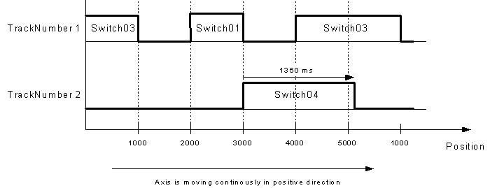
Assume the following parameter values set:
Parameter
Type
Switch01
Switch02
Switch03
Switch04
TrackNumber
INT
1
1
1
2
FirstOnPosition [u]
REAL
2000
2500
4000
3000
LastOnPosition [u]
REAL
3000
3000
1000
-
AxisDirection
INT
1=Pos
2=Neg
0=Both
0=Both
CamSwitchMode
INT
0=Position
0=Position
0=Position
1=TIME
Duration
TIME
-
-
-
1350
Assume further, that no on/off compensation nor hysteresis is employed. The figure demonstrates the behavior of the outputs,
when the axis is moving continuously in positive direction. The axis is a modulo axis with a modulo length of 5000 u.
TRUE: Execution of function block has not been finished
yet.
Error
BOOL
TRUE: Error has occurred within the function block.
ErrorID
SMC_ERROR
Error identification
SwitchCorrupted
INT
Signals potential problems that arise from compensation times:
Compensation times may lead to the case that the extrapolated position
passes one switching point several times before passing the other
switching point again.
As a consequence, a non-inverted switch may become inverted
(and the other way around).
In this case, this variable indicates the switch in concern.
There are two possible reasons:
noisy velocity-values,
“big” difference between on- and off-compensation.