「Kin_HGantry3」(FB)
- FUNCTION_BLOCK Kin_HGantry3 IMPLEMENTS ISMPositionKinematics_Offset,
ISMPositionKinematicsInternal、ISMKinematicWithInfo2
3 軸 H ガントリーの変換 FB です。
(Kin_HGantry2 を参照)
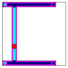
キネマティクス 構成は Kin_Gantry3 で説明する内容と似ています。 ただし、ドライブについては据え付けで取り付けます。 フレームの周囲にあるドライブベルトで Y 軸 レールとスライダーを移動します。 (横の画像を参照、ベルトをピンクで表示)
マシン座標系 (MCS) |
|
|---|---|
オリジン |
3 本すべての軸の位置の値が 0 である時の TCP の場所です。 |
X |
第 1 軸 (a0) の正の速度が第 2 軸 (a1) の同量の負の速度と一緒になって、純粋に X 軸に沿って正の方向への動作をもたらすように、X 軸は定義されます。 |
Y |
両軸にある同量の負の速度が、純粋に Y 軸に沿って正の方向への動作をもたらすように、Y 軸は定義されます。 |
Z |
第 3 軸 (a2) の方向へ直接対応します。すなわち、第 3 軸の正の速度が MCS で正の Z 方向に動作をもたらします。 |
The location of the tool coordinate system (TCS) relative to the MCS in zero position:
Tool coordinate system (TCS) |
|
|---|---|
オリジン |
Relative to MCS: dX = 0 dY = 0 dZ = 0 |
X |
Along the X-Axis of the MCS in positive direction |
Y |
Along the Y-Axis of the MCS in positive direction |
Z |
Along the Z-Axis of the MCS in positive direction |
変換は以下の軸構成に適しています (その他の構成は、A と B を交換することで達成可能です)。
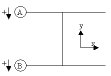
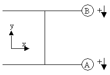
単一の軸の値には以下の解釈があります。
a0 |
マシン (A) の 第 1 軸の位置 |
a1 |
マシン (B) の 第 2 軸の位置 |
a2 |
マシン (Z) の Z 軸の位置 |
- 属性:
sm_kin_libdoc
Properties:
Methods:
Structure: