Creating a CODESYS Safety Extension Project
This describes how you can to create a simple safety project step by step and how you can load the safety application to the safety controller.
(1) Creating a safety project
After you start CODESYS with the installed CODESYS Safety Extension, click .
In the New project dialog, select the Empty Safety project template. This template is an empty project with the safety user configuration. For more information, see: Setting Up User Management in the Project.
Then enter a Name for the project in this dialog ("Project_Safety" in our example) and the desired storage location for the project and click the OK button to confirm the dialog.
(2) Adding a standard controller and a safety controller
In the next step, a standard controller is added to the project by selecting the Project_Safety project and then clicking Add Device in the context menu. Select the standard controller to which your safety controller is connected, or in which it is installed and click Add Device.
Then the safety controller is added to the standard controller by selecting the standard controller in the device tree and clicking Add Device in the context menu.
In the Add Device dialog, select the desired safety controller in the category and click the Add Device button to confirm your entry.
In the next dialog Login, specify a user who exists in the safety user configuration (see ) as a member of the Owner, Safety, or Safety.ExtendedLevel group. If the user configuration has not yet been adapted by the project manager (Owner) for the current project, you now need to enter ext as the user; the password is empty. This user is a member of the user group Safety.ExtendedLevel. Click OK to confirm the dialog. For more information, see: Setting Up User Management in the Project.
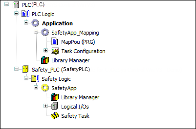
Together with the safety controller, the logical node point Safety Logic, the safety application object with Library Manager, the node point Logical I/Os, and the Safety task are also added.
(3) Inserting devices (safe device and standard device)
Then a fieldbus master and a fieldbus slave (PROFIBUS in the example) are added under the standard controller.
To do this, select the standard controller in the device tree and insert the master and then the slave using the Add Device command in the context menu.
The name of the respective device can be changed in the Name field in the Add Device dialog. When selecting the slave, care must be taken that a slave is selected that can be supplemented by a safe module.
Now insert the safe module under the slave via the Add Device command in the context menu and change the name of the device for the example to "SafeOut". In the Add Device dialog, you will find the safe modules in a subcategory of the fieldbus (in the example: Safe Modules subcategory in the Profibus category).
When inserting the safe module below the standard controller, the corresponding logical I/O is automatically inserted below the safety application.
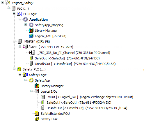
Figure 3. Device tree with inserted safe device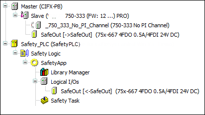
In this step, use the Add Device command in the context menu to insert a standard field device below the slave (in the example:
75x-5044DO/24V DC/0,5A) and in the insert dialog change the name to UnsafeOut. In order to be able to use the I/O data of the standard device in the safety application, a logical I/O must then be explicitly inserted below the safety application for this field device.In order to be able to use the I/O data of the standard device in the safety application, a logical I/O must then be explicitly inserted below the safety application for this field device.
To do this, select the Logical I/Os node point under the safety application and click in the context menu. In the Add Logical Device dialog in the Logical Devices, Generated logical devices category, select the device of the standard device that you have already inserted under the standard controller (in the example
75x667 4FDO 0.5A/4FDI) and confirm the dialog with the Addbutton. The name of the logical I/O can be changed to UnsafeOut in the Properties dialog.In order to connect this logical I/O with the standard field device under the standard controller, open the standard device with a double click and afterwards the DP modules I/O Mapping tab. In the Logical I/O mapping combo box, select the logical I/O that belongs to your standard field device (in the example:
UnsafeOut).
(4) Setting up a variable exchange with the standard controller
For the exchange of variables between the standard controller and safety controller, insert the Logical Exchange GVL object below the standard application and a logical exchange object below the safety application.
The logical exchange object is first added below the safety application. Select the Logical I/Os node point under the safety application and activate the command in the context menu. In the Add Logical Device dialog, select the suitable device in the Logical exchange device category of the Logical devices category, i.e. the desired data type and the exchange direction, in the example:
DINT 1xOut, enter the nameLxOutand click the Add button. When inserting the logical exchange device, it must be given the nameLxOutin order to be able to select this name later in the GVL.The corresponding logical exchange GVL is now added under the standard application. To do this, activate the command in the context menu. Now enter Logical Exchange GVL as the name in the Add Logical Exchange GVL dialog window and click the Add button.
In the open editor, now select the LxOut exchange object from the Logical Exchange Mapping combo box.
(5) Adding a POU and writing program code
In the Devices view, select the SafetyApp object and select the command in the context menu.
In the Add Extended POU (Safety) dialog, now enter the name "SafetyExtendedPOU", select PROGRAM as the POU type, and then click the Add button.
Important
In order to be able to add an Extended POU (Safety), you must be logged on as the "Owner" user or as a member of the "Safety.ExtendedLevel" group when using the safety user configuration.
The editor of the POU opens. In the editor, now the variables can be declared and the program code can be edited.
Now declare the variables listed in the illustration below in the declaration part of the editor. The declaration of the variables takes place via the Insert Variable Declaration command in the context menu. The local variables are declared with
VAR. The mapping variables of the logical I/Os are declared withVAR_EXTERNAL.Figure 4. Program of the safety application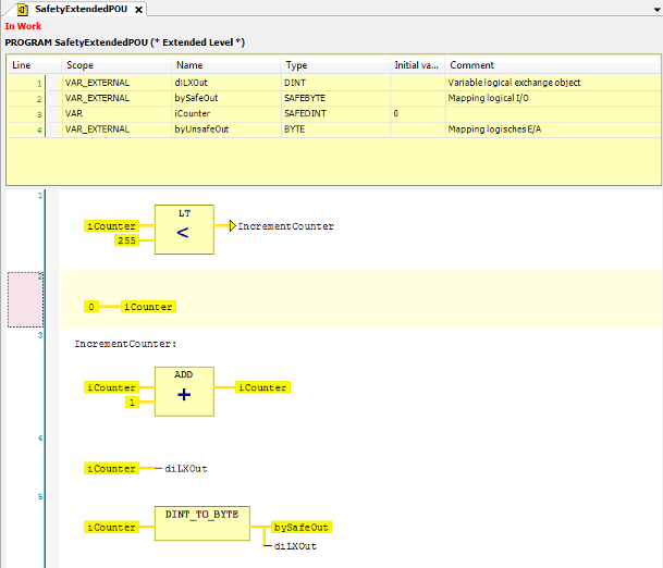
Subsequently, enter the program code listed in the above illustration into the implementation part of the editor Safety FBD Editor. The editor is used like the CODESYS FBD editor.
Networks are added using the Insert Network command in the Safety-FBD menu.
The operators are inserted using the Insert Box command in the Safety-FBD menu. In the same way, the Insert Jump, Insert Label and Insert Assignment commands can be found in the Safety-FBD menu.
Explanation of the program: In Network 1, a check is performed as to whether the counter iCounter is smaller than 255. If this is the case, then a jump takes place to the label IncrementCounter. Otherwise iCounter in Network 2 is set to 0.
In the Networks 3 and 4 (label IncrementCounter) the iCounter is incremented by 1 and assigned to the mapping variables of the logical I/Os. Before assignment to the mapping variables of the standard device and the safe device, the counter is converted from DINT to BYTE.
The diLXout variable can be processed further in the standard application.
(6) Editing the mapping variables in the logical I/Os
The variables declared in the program code as VAR_EXTERNAL are now entered in the logical I/Os as mapping variables.
The operators are inserted using the Insert Box command in the Safety-FBD menu. In the same way, the Insert Jump, Insert Label and Insert Assignment commands can be found in the Safety-FBD menu.
Open the
UnsafeOutlogical I/O with a double click and enter thebyUnsafeoutvariable as an output channel on the I/O Mapping tab.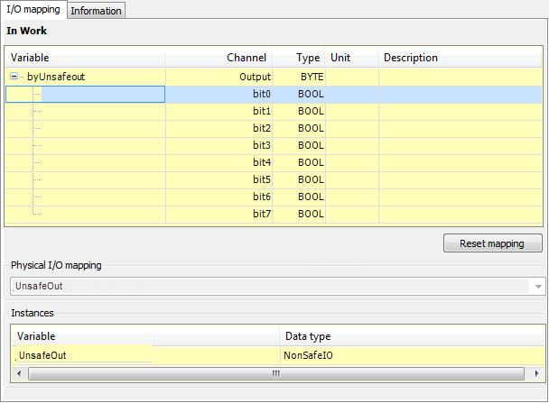
In the same way, enter the bySafeOut variable as an output channel in the I/O Mapping of the SafeOut logical I/O and the diLXOut variable on the I/O Mapping tab in the LXout logical I/O.
(7) Building the safety application
In the Build menu, click Build to compile the security application. The safety check for errors is also performed. Errors and warnings are displayed in the message window. If no errors occur, then the safety application can be loaded to the safety controller in the next steps.
(8) Communication settings
In the device tree, double-click the safety controller.
The Tab: Communication Settings opens.
Select your network (gateway) and scan the network for your device using the Scan network button. If your device is displayed, then select it and click the Set active path button.
(9) Logging in to the safety controller
Click to log in to the safety controller.
The Connect to safety device dialog opens.
This dialog serves to confirm the connection to the safety controller. The dialog explains the device-specific form of the confirmation (action on the device or identification).
Figure 5. Dialog 'Connect to safety device' in the variant: Entry of an identification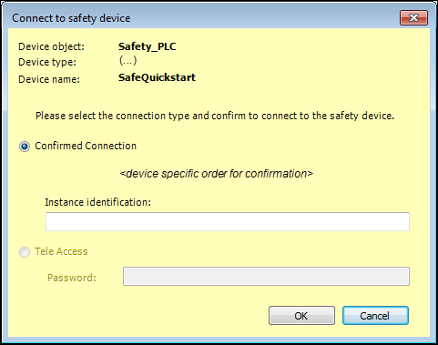
In the dialog, select the Confirmed Connection option in order to create an application.
In the dialog, enter the ID of the safety controller and confirm the dialog by clicking the OK button.
For more information, see: Connecting to a Confirmed Controller.
After the connection to the safety controller has been confirmed, a dialog opens where you can select whether you want to temporarily download your application to the controller or whether a boot application should be created from the application and stored on the controller. By clicking either the Yes, I have! Create boot application button or the Yes, I have! Download temporarily button, you also confirm that the organizational security has been established for the entire networked facility. For the example of these instructions, click the Yes, I have! Download temporarily button.
Figure 6. Dialog when logging in with confirmation of the organizational safety of the networked facility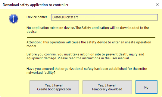
In the subsequent Authorization dialog, enter the password for the controller. (If no password has been set yet, then the default password is active; this can be, for example, the empty password, depending on the manufacturer.) Confirm the entry with the OK button.
You are now logged in to the safety controller. The application is checked and downloaded, and messages are displayed in the message window. After download, the security application is in STOP and unsafe state. (For more information, see: States of the Safety Controller)
Figure 7. Display in lower status bar after logging in
Now you can debug the application with the following functionalities: Start – Safety), Stop – Safety and Write Values – Safety/Force Values – Safety, Monitoring in Safety FBD Editor in Online Mode and Variable Declaration Editor in Online Mode or Create Boot Application.