Safety FBD Editor
This editor of the Safety Extended POUs and Safety Basic POUs is opened in a window that is divided into two sections and contains the Variable Declaration Editor in the upper section and the implementation part for the creation of the program code in the lower section.
The Pin information or, if the object version deviates from the pinned version or if the safety application has not yet been pinned, In work is displayed in the top line of the editor. For more detailed information about the Pin information, see Pinning. The following line contains the POU type (PROGRAM or FUNCTION_BLOCK, the name of the POU, the programming level (Basic Level or Extended Level) as well as the use (if applicable Single call, for further information see Safety POUs).
The Safety FBD editor is functionally based on the FBD editor of CODESYS V3 and is extended by safety specific functions. The use of the Safety FBD Editor corresponds to that of the CODESYS V3 FBD Editor. General editing commands (Copy, Paste, Cut, Delete, Undo, Find/Replace) and the commands of the Safety FBD category are available to the user.
Tip
The Cut, Copy, and Paste commands can only be executed between safety objects (POU), not between safety and standard objects (POU).
The general Delete editing command deletes an element from the FBD network. What is deleted depends on the cursor position where the command is executed. If an input or output of a box which represents a function block call is deleted, then the elements at the input or output are also deleted. If the main output of a FB call located within a network is deleted, then the entire tree to the left of this box output will be removed (i.e. including the block itself). If the box is the (right-hand) end of a network, then the last output (main output) can also be removed. The block is then retained and has no outputs.
For the individual commands of the Safety FBD category, see the Menu: Safety FBD chapter.
Tip
You can drag a variable from the declaration part to the implementation part of the FBD editor.
Important
The magnification tool ( ) in the safety FBD editor must not be used for verification and acceptance.
Options can be set for the editor in the Dialog: Safe FBD options.
Available scopes and data types, depending on the POU type and programming level of the POU can be found at Variables.
ToolBox
The Safety FBD Editor provides a ToolBox view, from which the individual programming elements can be inserted into the editor window by means of drag and drop. By default the ToolBox view is automatically opened next to the editor window and can also be explicitly opened if necessary using the ToolBox command in the "View" menu.
Input Assistant
The Input Assistant can be opened in the Safety FBD Editor by clicking the  button or by pressing the F2 key. To do this the cursor must be in a text field of the editor. The dialog offers all programming elements that can be inserted at the current cursor position.
Safe signal flow
The data flow of fail-safe signals of FBD programming is highlighted as follows:
Literals are highlighted in yellow.
SAFExxxvariables are highlighted in yellow.The data flow of
SAFEvalues intoSAFEvariables and into inputs of operators and function blocks is represented by thick yellow linesFunction blocks are displayed in yellow when they have at least one
SAFEoutputOperator call boxes are filled in with yellow if the output is
SAFE. This is the case under the following conditions:ANDoperator: The output isSAFEif at least 1 input isSAFE.All other operators, including conversions: The output is
SAFEif all inputs areSAFE.
AND operator with literal: TRUE, SAFE variables: bVarIn and bVarOut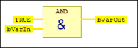
Change markings in the FBD editor
The differences to the previous version are marked in color after each editing operation. The marking of the last-performed action is always visible. All markings are removed on closing the POU.
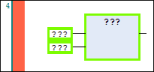
Green: Recently added networks or elements
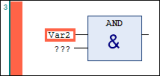
Red: Changes to an existing network/element
The network with the change is marked red.
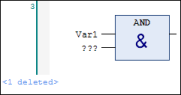
Blue: Deletion mark for deleted network or element
Var2