SMC_SmoothPath (FB)
FUNCTION_BLOCK SMC_SmoothPath
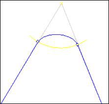
SMC_SmoothPath smoothes corners between adjacent elements by inserting
splines. See SMC_RoundPath for an alternative corner rounding
with circular arcs.
The cut distance, the distance between the start or end of the spline and
the corner, is always limited to the sum of dEdgeDistance and the value
of the g-code word D.
If input bSymmetricalDistances is set, the cut distance is further
limited to the minimum of half the length of the first element and
half the length of the second element.
If the sum of input variable dEdgeDistance and G-code word D is 0,
then no smoothing is done.
If one of the two elements is a G0 element, then no smoothing is done.
Details
All SMC_GEOINFO elements of the input structure SMC_OUTQUEUE are checked one after the other. The smooth-path functionality is executed for all elements between G51 and G50.
M-function at the smoothed corner
If there is a M-function at the corner that will be smoothed, then the M-function remains but is moved to the end of the smoothed corner. This behavior is consistent with the behavior of SMC_RoundPath .
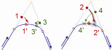
H-function at a smoothed corner
If there is a H-function bewtween the first cut point and the corner (1), the point is moved to the smoothed path (1’). The distance to the start point remains the same. If there a H-function between the corner and the second cut point (3) the point is also moved to the smoothed path (3’), so that the distance to the end point remains the same.
The position of the moved H-functions is limited so that they don’t cross the center of smoothed path. Otherwise the order of the H-functions might change (2’, 4’).
Example 1: Smoothing with splines
G-Code
N000 G01 X10 Y0 F100
N010 G51 D2 (smoothing with cut distance 2)
N020 G01 X10 Y20
N030 G01 X20 Y20
N040 G01 X20 Y0
N050 G50 (smoothing off)
N060 G01 X30
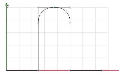
The following figure shows a path with smoothed corners. The smoothing is turned on at position X10 Y0 and is turned off at position X20 Y0. All corners between these positions are replaced by splines.
Example 2: Input bSymmetricalDistances
G-Code
N000 G01 X10 Y0 F100
N010 G51 D10 (smoothing with cut distance 2)
N020 G01 X10 Y20
N030 G01 X20 Y20
N040 G01 X20 Y0
N050 G50 (smoothing off)
N060 G01 X30
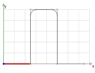
The example shows the result when the cut distance
is larger than half of the element. The following figure shows the
resulting path with bSymmetricalDistances = FALSE.
The element is too short, so it is completely replaced by two
splines.
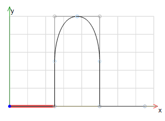
In the following figure bSymmetricalDistances is set, together
with bImprovedSymmetricCuts. At both
corners, half the length of the horizontal line limits the cut
distance to 5.
Example 3: Input eMode
G-Code
N000 G51 D10 (smoothing with cut distance 10)
N010 G01 X0 Y10
N020 G01 X10 Y10
N030 G01 X10 Y0
N040 G50 (smoothing off)
The default spline type for smoothing is SP_SPLINE3, i.e. a
third-degree polynomial in each dimension.
It is recommended to use SP_SPLINE5_MIN_CURVATURE.
Fifth-degree polynomials have the advantage that they are smooth up to
the curvature (second derivative).
This results in a limited jerk.
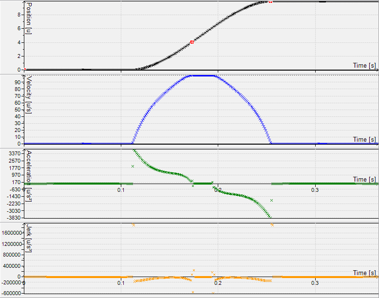
Dynamic curves along the X-axis with eMode = SP_SPLINE3
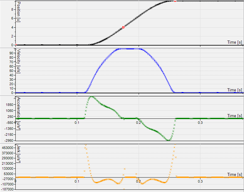
Dynamic curves along the X-axis with eMode = SP_SPLINE5
A smoothing element always uses the tool correction information (i.e. lengths and diameter) of the preceding element.
Note
PROBE movements such as G31 are not supported. The error
SMC_PROBE_G31_NOT_ALLOWED is reported if a PROBE movement
is encountered while corner smoothing active.
- InOut:
Scope
Name
Type
Initial
Comment
Input
bExecuteBOOLStarts on rising edge.
bAbortBOOLIf
TRUE, the current processing of this function block is abortedbAppendBOOLAs long as this input is set to
FALSE, thepoqDataOutqueue will be cleared at each reset. As long as it is set toTRUE, newly incoming data will be written to the end of thepoqDataOut-queue.poqDataInPOINTER TO SMC_OUTQUEUE
The input path queue
dEdgeDistanceLREALThis input variable contains the value, which – added to the value of the
Dword – determines the (maximum) cut distance to the corner. This value may be modified online.dAngleTolLREAL0.001
This input defines the value for the angle tolerance, up to which a path bend should not be smoothed.
nSizeOutQueueUDINTThis variable contains the size of the data buffer
pbyBufferOutQueuein bytes.The list of SMC_GEOINFO structure objects will be written to. This buffer must be large enough to hold at least five SMC_GEOINFO objects. Otherwise, the function block will not execute any actions at all. Its size may be predefined, but may be modified later only during a reset. It is recommended to create the buffer as described by the example below:
ExampleBuf: ARRAY[1..50] OF SMC_GeoInfo;The correct buffer size will then be retrieved by use of the operator
sizeof(ExampleBuf).pbyBufferOutQueuePOINTER TO ARRAY [0..0] OF SMC_GEOINFO
This input must point to the first byte of the memory area being allocated for the SMC_OUTQUEUE structure. This area must be at least as big as defined in
nSizeOutQueue. Typically the allocation of the memory buffer is done within the declaration part of the IEC-program by defining a byte-array (ExampleBuf:ARRAY[1..50] OF SMC_GEOINFO;). The value may be predefined, but may then be modified during a reset only.eModeSP_SPLINE3
Determines which kind of spline is used for smoothing. It is recommended to use SMC_SMOOTHPATHMODE.SP_SPLINE5_MIN_CURVATURE.
bSymmetricalDistancesBOOLTRUE
If
bSymmetricalDistancesis set, the cut distance is limited to half the length of the shorter element. Otherwise the cut distance defined in theDword is used.bImprovedSymmetricCutsBOOLIf
bSymmetricalDistancesis set, the first element is cut at most in half. If the optionbImprovedSymmetricCutsis set, this limitation is lifted. In some cases this results in a better smoothing. Only has an effect ifbSymmetricalDistancesis set. It is recommended to set this input toTRUEifbSymmetricalDistancesis set.eAddAxModeSPAA_LATE
The way how additional axis are treated. If
SMC_SmoothMergeis used, this parameter should be set to modeSPAA_EXACT.dMinimumCurvatureRadiusLREALIf a spline, that would be inserted in a edge, contains a position where its curvature radius is less than this parameter, this edge is not smoothed. In this situation no spline is inserted, but the original path is maintained and a stop is executed in the edge.
bCheckCurvatureBOOLIf
TRUE, it is checked if the curvature of adjacent elements is equal. If this is not the case, the path will be smoothed.dRelativeCurvatureTolLREAL0.001
The maximum allowed relative difference in the curvature. Only used if
bCheckCurvatureisTRUE.bCheckAddAxVelJumpBOOLIf
TRUEthe axis A, B and C are checked for velocity jumps. Should be set ifSMC_SmoothMergeis used.dMaxAddAxVelDifferenceLREALThe maximum allowed velocity jump [units/sec]. This input is evaluated if
bCheckAddAxVelJumpisTRUE. Recommended:maxAcceleration * taskCycleTimeOutput
bDoneBOOLThis output will be set to
TRUEas soon as the input data frompoqDataInhas been processed completely. Thereafter, the module will not perform any further actions until it gets reset. If inputbExecuteisFALSE,bDonewill be reset toFALSE.bBusyBOOLTRUE, while execution of function block is not finishedbErrorBOOLSignals, that an error has occurred within the function block
wErrorIDSMC_ERRORError identification
poqDataOutPOINTER TO SMC_OUTQUEUE
The output path queue
udiStopsDueToCurvatureRadiusUDINTNumber of edges that could not be smoothed because of the
dMinimumCurvatureRadiussetting
Structure: