Preparation of development environment and project
Default settings
Below you can see which default settings are available for visualizations.
Scope | Setting Location | Setting |
|---|---|---|
Throughout CODESYS |
| |
Adaptation of the visualization menu | ||
Throughout the project |
| |
Project-specific | Updates of the visualization profile, visualization styles, and visualization symbol libraries | |
Throughout the application |
| |
Single visualization |
TipYou can determine the visualization type on the Visualization tab. | |
Display variant of an individual visualization |
|
Creating visualization objects in the project
For each visualization, you insert a Visualization object into your project like any other object. This also applies to visualizations that should be used later only within other visualizations. You can insert the new visualization object directly below an application, or below the root node of the Devices view (for availability throughout the entire project).
The required base libraries and other objects, such as the Visualization Manager, are inserted automatically. When you insert the visualization object below an application, the subordinate objects for the display variants supported by the device are also displayed.
Every visualization object can be edited separately in the visualization editor.
The following steps describe a simply example for creating an object for an application-specific visualization.
Open a project with an application.
Select the application in the device tree. In the context menu, click .
The Add Visualization dialog opens. There is at least the standard entry VisuSymbols Vx.x.x. (System), possibly also other symbol libraries if they have been installed.
Accept the default name
Visualizationfor the visualization. Select the VisuSymbols option.The visualization symbols (graphics objects) which hare contained in the library are now available in your visualization project.
Click Add to close the dialog.
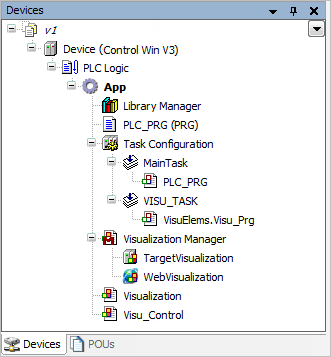
In the device tree, the Visualization Manager and Visualization objects are inserted below the application. Depending on the device in use, the TargetVisu and/or WebVisu objects are also created below the Visualization Manager.
If a TargetVisu object or WebVisu object is created, then a VISU_TASK object is also created below the task configuration with an implicit program call.
The required visualization libraries are added automatically in the Library Manager of the application.
The visualization editor opens with the Visualization editor view and the Visualization ToolBox and Properties views.
In the Visualization ToolBox view, there is a Symbols button for viewing the symbols from the library
VisuSymbols.library.In the visualization editor, create the desired visualization.
Example of a device tree with two inserted visualizations:
Tip
You can create a user interface from multiple visualization objects and link their pages using the Frame or Tabs structure elements. The Frame structure element references a visualization object whose images then appear as one page of a versatile user interface. The Tabs structure element can display multiple visualizations.
You can display dialogs to request information from the visualization user in your user interface. To output information, you can display the message view. You design dialogs and messages as a special visualization object (type: Dialog) whose image appears when the visualization user performs a certain input action. Usually a dialog opens after clicking a button.
Tip
For creating an application-dependent visualization, insert the visualization object directly below the root node of the device tree. This corresponds to insertion in the POUs view. In this case, a Visualization Manager is not created with objects for the display variants.