Kin_Scara3_Z (FB)
FUNCTION_BLOCK Kin_Scara3_Z EXTENDS Kin_Coupled
Transformation FB for Scara3 kinematics with an additional Z-axis.
The Selective Compliance Assembly Robot Arm (SCARA) is a special type of industrial robot which resembles to an human arm. A Scara3 system exhibits three axes and three degrees of freedom. However, the motion is still limited to the X-Y-plane.
Machine coordinate system (MCS) |
|
|---|---|
Origin |
The intersection of axis 0 and the X-Y-plane. |
X |
Defined by the direction the first arm points to when the first rotary axis (a0) is at 0°. |
Y |
The Y axis results automatically from the definitions of the X and Z axis by rotating the X axis by +90° around the Z axis. |
( Z ) |
This FB features an additional linear axis (a3) perpendicular to the X-Y-plane. The Z axis corresponds directly to the positive direction of this additional axis. |
The location of the tool coordinate system (TCS) relative to the MCS in zero position:
Tool coordinate system (TCS) |
|
|---|---|
Origin |
Relative to MCS: dX = dArmLength1 + dArmLength2 + dArmLength3 dY = 0 dZ = 0 |
X |
Along the X-Axis of the MCS in positive direction |
Y |
Along the Y-Axis of the MCS in positive direction |
Z |
Along the Z-Axis of the MCS in positive direction |
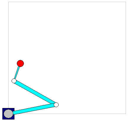
The system consists of
a rotary axis a0 that turns the robot around the Z axis
the first joint with length dArmLength1,
a second rotary axis a1 that turns the following parts of the robot around the Z axis,
the second joint with length dArmLength2,
a third rotary axis a2 that turns the following parts of the robot around the Z axis,
the third joint with length dArmLength3 and
a linear axis (a3) that is orientated in direction of Z.
There are two configurations that can be switched with the input xElbowRight of Kin_Scara3_Z_Config.
The single axes values have the following interpretation:
a0 |
position of the first rotary axis around Z in degrees |
a1 |
position of the second rotary axis around Z in degrees |
a2 |
position of the third rotary axis around Z in degrees |
a3 |
position of the linear axis in direction of Z axis |
The zero position of the kinematics can be adjusted by defining
constant offsets for the axes. See inputs dOffsetA1, dOffsetA2,
dOffsetA3 and dOffsetZ.
Changing the offsets affects the location and orientation of the TCS.
- Attributes:
sm_kin_libdoc- InOut:
Scope
Name
Type
Comment
Inherited from
Input
itfPosKinitfOriKindArmLength1LREALArm length of 1st joint
dArmLength2LREALArm length of 2nd joint
dArmLength3LREALArm length of 3rd joint
dOffsetA1LREALAdditional offset of axis A1. This offset is subtracted before the forward transformation and added after the inverse transformation.
dOffsetA2LREALAdditional offset of axis A2. This offset is subtracted before the forward transformation and added after the inverse transformation.
dOffsetA3LREALAdditional offset of axis A3. This offset is subtracted before the forward transformation and added after the inverse transformation.
dOffsetZLREALAdditional offset of axis Z. This offset is subtracted before the forward transformation and added after the inverse transformation.
Properties:
NumAxes, inherited from Kin_Coupled
Methods:
ActivateAutomaticRotaryPeriods, inherited from Kin_Coupled
AxesToCartesian, inherited from Kin_Coupled
AxisSettings, inherited from Kin_Coupled
CPConnectible, inherited from Kin_Coupled
CartesianToAxes, inherited from Kin_Coupled
GetAxisMapping, inherited from Kin_Coupled
GetAxisProperties, inherited from Kin_Coupled
GetConfigurationDataSize, inherited from Kin_Coupled
GetDefaultConfigurationData, inherited from Kin_Coupled
GetFlangeOrientationImageTotal, inherited from Kin_Coupled
GetFlangeOrientationImageWithOri, inherited from Kin_Coupled
GetPeriods, inherited from Kin_Coupled
GetPosAndToolKinematics, inherited from Kin_Coupled
IsConfigSingular, inherited from Kin_Coupled
IsInitialized, inherited from Kin_Coupled
IsSingularity, inherited from Kin_Coupled
JoinConfig, inherited from Kin_Coupled
SplitConfig, inherited from Kin_Coupled
Structure: