Kin_Tripod_Rotary (FB)
- FUNCTION_BLOCK Kin_Tripod_Rotary IMPLEMENTS ISMPositionKinematics_Offset,
ISMPositionKinematicsInternal, ISMKinematicWithInfo2, ISMKinematicWithInitialization
Transformation FB for Tripod kinematics with rotary axes
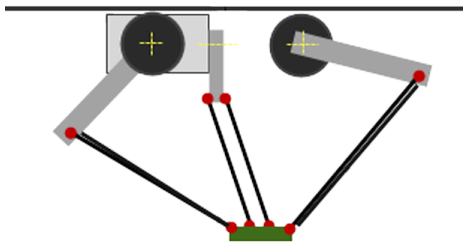
In the kinematic design for a tripod with rotary drives, three rotary drives are connected to the tool plate by arms and connecting rods.
Machine coordinate system (MCS) |
|
|---|---|
Origin |
Defined as the midpoint of the tool plate when all three upper arms (i.e. the ones directly connected to A0, A1, and A2 respectively) are in horizontal position. |
X |
Points from the origin and away from the point P of the first axis (A0). |
Y |
Defined by X and Z so that the MCS becomes right-handed. |
Z |
Orthogonal to the tool plate. Points from the tool plate towards the motors. |
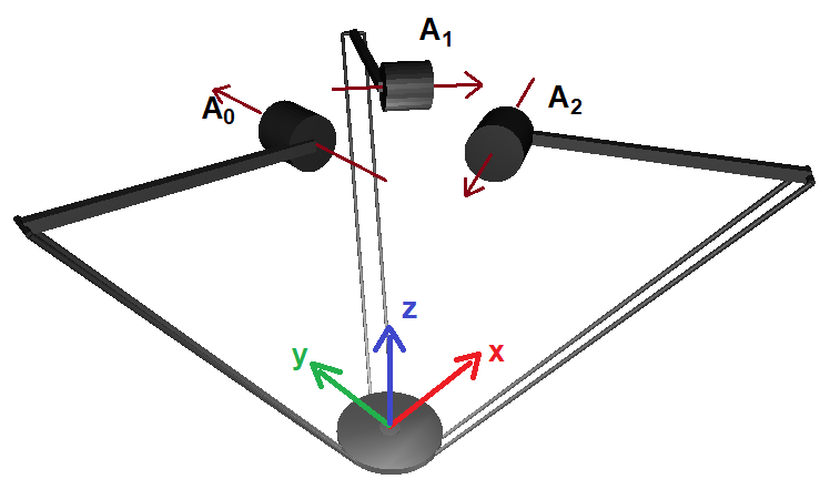
The location of the tool coordinate system (TCS) relative to the MCS in zero position:
Tool coordinate system (TCS) |
|
|---|---|
X |
Along the X-Axis of the MCS in positive direction |
Y |
Along the Y-Axis of the MCS in positive direction |
Z |
Along the Z-Axis of the MCS in positive direction |
The image shows the zero position of all axes (the three upper arms are horizontal). The MCS is displayed in the tool plate. Additionally, the arrows at the axes A0, A1, and A2 show the direction of rotation according to the right-hand-rule.
Mechanical requirements:
The lengths of all three arms must be equal.
The lengths of all connecting rods must be equal.
The distance between the two connecting rods in each pair must be equal.
The members of AXISPOS_REF have the following interpretation:
a0 |
position of the 1st axis of the machine (A0) |
a1 |
position of the 2nd axis of the machine (A1) |
a2 |
position of the 3rd axis of the machine (A2) |
- Attributes:
sm_kin_libdoc- InOut:
Scope
Name
Type
Initial
Comment
Input
dArmLength1LREALLength of the upper arm connected to the motor.
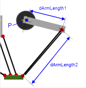
dArmLength2LREALLength of the lower arm (from the upper arm to the tool plate).
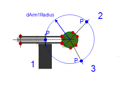
dArm1RadiusLREALThe radius of the circle that is established by the three points P of the drives.
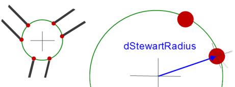
dStewartRadiusLREAL0
The radius of the circle that is established by the six points where the connecting rods connect to the tool plate.
dDistanceLREALDistance between the two connecting rods in one pair.
dMaxAngleBallJointLREAL45
Maximum angle in +/- for the ball joints.
Properties:
Methods:
Structure:
- AxesToCartesian (Method)
- AxesToOrientation (Method)
- CartesianToAxes (Method)
- CartesianToAxes_Offset (Method)
- GetAxisProperties (Method)
- GetKinematicsName (Method)
- GetOrientationImage (Method)
- Initialize (Method)
- IsInitialized (Method)
- IsSingularity (Method)
- NumAxes (Property)
- ProjectPosition (Method)