SF_ResetButton
Applicable Safety Standards
SF_ResetButton is a certified PLCopen function block. For detailed information about the applied standards , see: "PLCopen – Technical Committee 5 – Safety Software"
Important
The requirements which are listed in the standards must be met by the user.
Interface Description
This function block adds the trailing edge functionality to all the function blocks with reset input with rising edge detection. This can be used to comply with EN ISO 13849-1:2015.
Name | Data Type | Initial Value | Description, Parameter Values |
|---|---|---|---|
|
|
| Input which should be connected to the
|
|
|
| Variable Input of reset button
|
|
|
| Constant; Valid in trailing mode Minimum time that the reset switch has to be actuated. If the reset button is pushed shorter than this time, the reset is ignored. Typical value: 350 ms Absolute minimum value: 100 ms Minimum value: 2 PLC cycles |
|
|
| Constant; Valid in trailing mode Maximum time that the reset switch can be actuated. If the reset button is pushed longer than this time, the reset is ignored. Typical value: 2 s |
Important
The ResetOut output is a rising edge (R_TRIG) pulse of length of one FB cycle, which can be connected to any FB which has a reset input, and as such is compliant to the PLCopen Safety FBs version 1.0.
The ResetRequested input is connected to the ResetRequest output of the relevant FB. With this the timing interval is controlled during which the Reset Button needs to be checked.
This FB uses S_AutoReset.
Name | Data Type | Initial Value | Description, Parameter Values |
|---|---|---|---|
|
|
| |
|
|
| Pulse for the initiation of the reset procedure This pulse is generated after the falling edge. Pulse output with rising edge first. At least 1 cycle |
|
|
| |
|
|
| See Diagnostic Codes |
Functional Description
For the functional description, see ISO 13849-1:2015, Section 5.6 "Reset Behavior".
Inputs | Outputs | ||||||
|---|---|---|---|---|---|---|---|
|
|
|
|
|
|
|
|
| --- | --- | --- |
|
|
|
|
|
| > = 100 ms |
|
|
|
|
|
|
| Watchdog is started |
|
|
|
| |
|
|
|
|
|
|
| |
|
|
|
|
|
|
| |
With the next call, there is an automatic transition from |
| ||||||
Tip
In the logic table, an arrow -> stands for a transition. TRUE -> FALSE means that the value of the variable has changed from TRUE to FALSE.
State diagram

Tip
Note: The transition from any state to the Idle state due to Activate = FALSE is not shown. However these transitions have the highest priority.
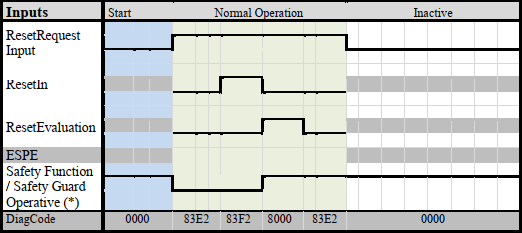
Typical Timing Diagrams
Error Detection
If the input ResetIn = TRUE when ResetRequested = TRUE, an error is generated.
If the input ResetRequested = TRUE and ResetIn = TRUE and the time input TrailingMinimum is not reached or the input TrailingMaximum is exceeded, an error is detected.
Error Behavior
In case of a static TRUE signal at the ResetIn input, the DiagCode output indicates the relevant error code and the Error output is set to TRUE.
FB-Specific Error and State Codes
| State Name | State Description and Output Setting |
|---|---|---|
|
|
|
|
|
|
|
|
|
|
|
|
| State Name | State Description and Output Setting |
|---|---|---|
|
| The function block is not active (initial state)
|
|
| The function block is enabled. Waiting for
|
|
|
|
|
| Valid reset behavior was detected. The state is valid for at least one cycle and will automatically transfer to
|