General Rules for Safety-Related Function Blocks
These programming rules correspond to the "General Rules for Safety-Related Function Blocks" of PLCopen. They apply to PLCopen-compliant function blocks.
FB-Specific Rules
Important
When using PLCopen function blocks, the user has to make sure that in the application the function block is called at least one time in each cycle.
Default signal | All safety-related Boolean I/O signals have the default safe value |
Signal level | The value of
This reflects the functionality of the IEC 61131 environments, such as the rules of the default value and that all outputs are set to |
Missing I/O parameters | Missing parameters are permitted. Default values apply. These default values shall under no circumstances lead to an unsafe state. Default values, including their attributes ( |
Start behavior | Initially, the outputs are set to the default values. After the first call of the function block, the outputs are valid. There is a consistent start behavior (cold start). |
Timing diagrams | Timing diagrams, as shown at the FBs, are provided for explanation only. They do not represent the exact timing behavior. The exact timing behavior depends on the implementation. |
Error handling and diagnostics | All safety-related function blocks have two error-related outputs: The rule for safety-related environments is that the switching of a safety-related function has the highest priority. Furthermore, the following switching must have sufficient time for the diagnostics, either in the functional program or the operator interface. |
General Input Parameters
Name | Data Type | Description |
|---|---|---|
|
| Variable or constant for the activation of a FB Initial value is This parameter can be connected to the variable, which represents the status (active or not active) of the relevant safety device. This makes sure that no irrelevant diagnostic information is generated if a device is disabled.
If no device is connected, then a static |
|
| Every Only variables may be assigned. |
|
| Variable or constant
Note the Safety Notices for |
|
| Variable or constant
Note the Safety Notices for |
|
| Variable. Initial value is Depending on the function, this input can be used for different purposes.
This function is active only on a signal change from Note the Safety Notices for The appropriate meaning must be described in every function block. |
Safety Notices for S_StartReset
S_StartReset
This automatic start shall be activated only if it is ensured that no hazard can occur at the start of the safety controller. Therefore, the use of the "automatic start" feature of the function blocks requires implementation of other system or application measures. This must ensure that unexpected (or unintended) startup does not occur.
Caution
If the input is linked to a variable (and not to FALSE), then additional validation measures must be defined for it.
Safety Notices for S_AutoReset
Caution
The automatic restart shall be activated only if is it ensured that no restart of the machine can occur through release of the emergency stop button. Therefore, the use of the "automatic restart" feature of the function blocks requires implementation of other system or application measures. This must ensure that unexpected (or unintended) restart of the machine does not occur.
Caution
If the input is linked to a variable (and not to FALSE), then additional validation measures must be defined for it.
Safety Notices for Reset
Caution
A SAFEBOOL must be connected instead of a BOOL depending on the safety requirements. See also: Function Block: SF_ResetButton.
General Output Parameters
Name | Data Type | Description |
|---|---|---|
|
|
|
|
| Every |
|
| Output indicating that the FB is active and the primary safety function is demanded (e.g. related to the safety functionality). Other safety-related input parameters are not considered (e.g.
|
|
| Output which can be used to signal the operator to press the reset functionality to continue
|
|
| Error flag (same as "K1/K2" LED of a safety relay)
Useful in debug mode as well as for further processing in the functional program. |
|
| Diagnostic register All states of the FB ( Useful in debug mode as well as for further processing in the functional program. |
Diagnostic Codes
A transparent and uniform diagnostic concept forms the basis of all function blocks. Thus, it is ensured that, regardless of the supplier's implementation, uniform diagnostic information is available to the user in the form of DiagCode. If no error is present, then the internal state of the function block (state machine) is indicated. An error is indicated via a binary output (Error). Detailed information about internal or external function block errors can be obtained via DiagCode. The function block must be reset via the different reset inputs.
| Description |
|---|---|
| The FB is not activated. This code represents the Idle state. For a generic example, the I/O setting for could be:
|
| The FB is activated without an error or any other condition that sets the safety output to
|
| An activation has been detected by the FB and the FB is now activated, but the
|
| The activated FB detects a safety demand, e.g.
|
| The safety output of the activated FB has been disabled by a safety demand. The safety demand is now withdrawn, but the safety output remains
|
| Description |
|---|---|
| X = System or device-specific message. This information contains the diagnostic information for the system or device, and is mapped directly to the Note: |
Generic state diagram
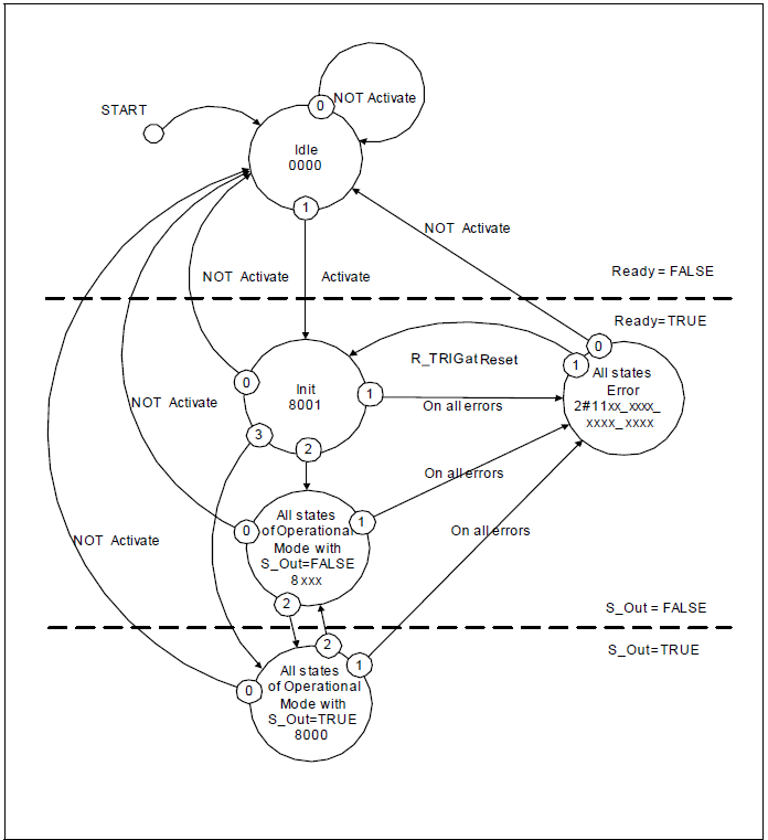
A general overview of the states and transitions are displayed. Some transitions are not named here. This means that they are FB-specific and are described with the relevant FBs.
The diagram shows three areas:
At the top, the FB is not active. It is in the Safe state (safe outputs are
FALSE).In the middle, the FB is active. It is in the Safe state (safe outputs are
FALSE).At the bottom, the FB is in the normal state. The safe outputs are
TRUE.
The first horizontal line in the state diagram shows the transition from a non-active FB to an active FB.
The second horizontal line shows the transition from a non-safe state to a safe state of the FB.
The priorities of possible parallel transitions are indicated by numbers (
0= highest priority).State bubbles contain the state name and hexadecimal DiagCode.
Conditions
OR,AND, andXORare used as logical operators andNOTis used as negation.Within the FB description, the starting state is
Idle, with the transitions to operational states via theInitstate.The transition from any state due to
Activate=FALSEchanges directly to theIdlestate (0= highest priority reserved forActivate=FALSE). For greater clarity, these transitions are not shown in each state diagram. But they are mentioned as a footnote to each state diagram.For reasons of clarity, the output setting is not described in the state diagram. An explicit truth table containing the states of the FB outputs is part of each FB specification. In addition, the FB-specific error and state codes are also described.
Note to transition from
8xx0to0000: Certain applications (like presses) need to finalize their cycle without the danger of any risk. In that case, the transition can be delayed.
| State Name | State Description and Output Setting |
|---|---|---|
|
|
|
| State Name | State Description and Output Setting |
|---|---|---|
|
|
|
| Init state and all states of operating modes where |
|
| All states of operating mode where |
|