Getting Started
Configuring the redundancy system
User Management
If a user management is used on the PLC, then you need to configure the same user name and the same password for access to both PLC devices. Otherwise, online services such as write variable or online change are not transmitted to the currently inactive PLC.
The devices which you want to operate redundantly each require a redundancy-capable runtime system with the CmpRedundancy and CmpRedundancyConnectionIP redundancy components. The top device in the device tree is usually the device that controls actively. The settings of the device are automatically applied as the PLC 1 settings for the redundancy configuration. The redundant device is configured as PLC 2 in the redundancy editor.
The devices can exchange their roles.
Requirement: The devices are running. A standard project is open in CODESYS Development System. The communication parameters are set for PLC 1.
In the device tree, select the application and add the Redundancy Configuration object.
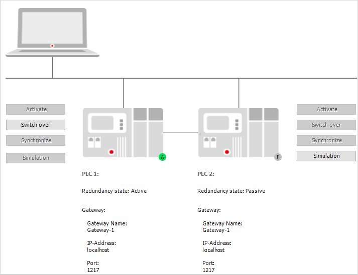
The Redundancy Configuration editor opens. The redundancy system is displayed graphically on the Redundancy State tab. The current communication settings of PLC 1 have been applied by the device editor and are already displayed.
Note
If PLC 1 reports the Components not loaded redundancy state, then the redundancy components are not active in its runtime system.
Click the Set Active Path PLC 2 button.
The Select Device dialog opens.
From the list of detected devices, select one as PLC 2.
The communication settings are applied and displayed in the graphic below PLC 2 (Gateway).
Select the Redundancy Settings tab and then the Redundancy Link tab.
Click the Browse button for the IP address PLC 1 and IP address PLC 2 settings.
Note: Redundancy uses its own protocol regardless of the CODESYS communication protocol.
The IP address of the respective device is listed.
Select the desired entry and click OK to confirm your selection.
The IP address has been applied. Make sure that both IP addresses are configured.
Example:
IP Address SPS 1 0001
IP Address SPS 2 0101
Port     1205
Click the General tab.
Configure your application and the fieldbus.
Redundancy task name: For example
MainTaskas the task is name in the projectTimeout (ms):
30Tip
Specify a realistic value for the timeout between two PLCs.
Synchronization timeout (ms):
0Click the Write button.
The redundancy settings are applied to the PLC. But they are not written to the CFG file yet. This is done only when the PLC is stopped. For this reason, both PLCs are stopped in the next step.
Click .
A message view is displayed, prompting for the desired kind of login.
Select Login with download.
The application is downloaded to PLC 1.
Stop both PLCs. (Here we do not mean stopping the application by means of the Online – Stop command, but stopping the runtime system.)
Start only PLC 1.
The boot project is downloaded to PLC 1. PLC 1 is in standalone mode. Afterwards, start only PLC 2.
Now start PLC 2.
When starting, the synchronization is performed. The application and data are transferred from PLC 1 to PLC 2 . Finally, PLC 1 is active and PLC 2 is running in standby mode.
Using a redundant control system with a visualization
You can connect visualizations, which are run as CODESYS WebVisu in a browser, with the redundant control system. The visualization clients will continue to run almost seamlessly in the event of a switchover.
Tip
Similar configurations are also possible based on a CODESYS HMI when these are run redundantly.
Open the redundancy editor, click the Redundancy Settings tab, and then click the Visualizations tab.
Select the Enable option.
The redundant control system with a CODESYS WebVisu link is enabled.
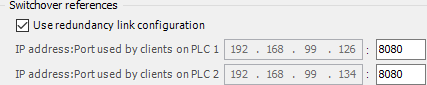
Select Use redundancy link configuration.
The settings of the redundancy link between the PLCs are applied for the web server connection. This is possible when the web visualization accesses over the same network connection that is also used for the redundancy link.
Example: