Basics
Important
The display of various elements of the ladder diagram – such as network titles and network comments – is controlled via the settings in the LadderEditor.prefs file.
Differences as compared to the ladder diagram in CODESYS 3
In CODESYS 3, with the CODESYS Ladder and CODESYS LD FBD add-ons, two variants of the ladder diagram are provided: Ladder Diagram (LD) and Ladder Diagram (LD2). The ladder diagram provided in CODESYS 4 is similar to LD2.
Ladder diagram in CODESYS 4
The required elements are available in the element bar. In the editor, commands are provided in the context menu, which refers to the selected element or a selected insert position. There is no menu.
Ladder diagram in CODESYS 3
The commands for the ladder diagram are provided in the Ladder Diagram menu, and the elements are provided in the Toolbox view. Commands can also be selectively accessed via the context menu.
The following functionality is only available in the ladder diagram in CODESYS 3:
The
AND,OR,ADD,MUL, andSELblocks can be extended to include input pins: Add Input Pin command.Unassigned input or output pins are removed from a block: Remove Unused Pins command.
A visualization can be generated for a POU in LD: Generate SFC/LD Visualizations command.
An ST block in the ladder diagram (LD) allows for the execution of program parts in the ST implementation language within a LD network. This is particularly advantageous for complex calculations, conditional instructions, and data manipulation: Insert ST Block command.
The following options in online mode are available only in the ladder diagram in CODESYS 3:
Monitoring current signal and variable values (inline monitoring)
Forcing and writing variables
Debugging using breakpoints
For more information about LD programming in the CODESYS 3 IDE, see the following: Help for CODESYS Ladder
Layout of a Ladder Diagram
In the LD editor, the elements are provided in the element bar and in the context menu.
Element | Element bar | Context Menu Commands | Editor | Description |
|---|---|---|---|---|
Bus bar | 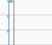 | The black vertical line represents the bus bar. It connects the numbered networks to form an interconnected ladder diagram. The networks are processed in order along the bus bar from top to bottom. | ||
 | Command: Network | A ladder diagram has at least one network. A network starts on the left at the bus bar and is connected to an output or coil via the signal path of the elements. A network roughly corresponds to an instruction – meaning a line of code in the ST POU which ends with a semicolon. It represents a line of code where, for example, an expression or a call can be programmed. | ||
Network, Title | 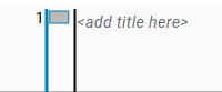 | Title for a network In the preferences, you can specify if the title should be displayed. | ||
Network, Comment | 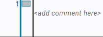 | Comment for a network In the preferences, you can specify if the comment should be displayed. | ||
Network, Jump label | 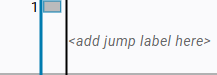 | Jump label for a network A jump label defines a jump target within the ladder diagram. One jump label is allowed per network. Initially, the placeholder text "add jump label here" will be displayed. This is visible when the focus is on the jump label. | ||
Current path | The horizontal line in the network can be read as the current path and connects the elements from the bus bar to the last element. The current path is displayed as soon as an element is added to the network. The elements can be connected along the current path in a series or in parallel. This makes it possible to route the path via one or more branches. The logic is read from left to right. Elements connected in a series are AND-ed. Elements in a parallel branch are OR-ed. | |||
 | Command: Contact | Contact for a Boolean input A contact represents a Boolean input signal. Depending on the signal state, the contact is conductive (closed) or non-conductive (open). The signal line is evaluated from left to right. | ||
 | Command: Coil | Coil for a Boolean output A coil represents a Boolean output signal. If the signal line is conductive up to the coil, then the output signal is set. Otherwise, it will be reset. This works similarly to an assignment operator. The signal line is evaluated from left to right. | ||
 | Command: Block | A block is an element that executes a complex function block. When a block is inserted, the network is first extended to include an empty block with a placeholder function. Then you can assign a function or a function block instance to the block. This determines the layout and design of the block, as well as the number of inputs and outputs. The EN/ENO mechanism is added by default. | ||
 | Command: Jump | The jump element executes a jump to a jump label in another network. The jump label is located at the beginning of the network, which is jumped to and then executed further. | ||
 | Command: Return | 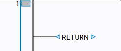 | When the return element is connected, the execution of the current POU is terminated prematurely. The program process then jumps back to the calling block. No further instructions will be executed. | |
 | Command: Input | Input element primarily intended for a non-Boolean value | ||
 | Command: Output | Output element primarily intended for a non-Boolean value |
Insert Positions
The insert positions which are valid for an element are essential for programming a circuit.
After you have selected an element in the element bar and then dragged the cursor back into the editor area, the valid insert positions will be displayed there. Drag the selected element to the desired position. Drop it only when the cursor shows a small plus sign to indicate that it is a valid position.
Insert positions are displayed as different symbols. Each symbol represents a possible position in the ladder diagram and indicates how the element could be connected to the neighboring elements.
Rectangle:

Insert position to the right of elements which have already been inserted
Rhombus:
 for inserting in a series
Insert position to the left of elements which have already been inserted
Triangle:
 ,
, 
Insert position after a branch on a parallel connection which runs down (triangle points downwards) or up (triangle points upwards)
Insert Positions | Context | Description |
|---|---|---|
| 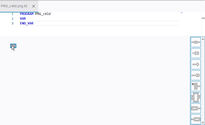 | Initial insert position When you move the mouse pointer over a network, bus bar, current path, or element, icons for insert positions and input fields for titles, comments, or jump labels will be displayed. These show the available programming options. |
| 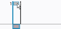 | Insert position for a new network above the existing network For example, when you select a contact in the element bar, an additional contact will be inserted into the new network. |
| 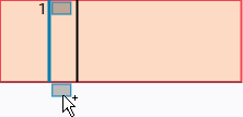 | Insert position below the existing network |
| 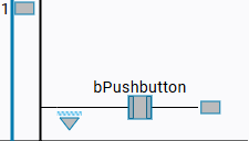 | Insert position at the end of the line The rectangle is displayed when there is neither a coil nor an output in the connection. |
| 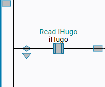 | Insert position to the left of elements which have already been inserted The rhombus marks a position where another element is inserted in a series before the existing elements. |
| The downward-pointing triangle marks an insert position where an element is inserted onto a parallel connection after a branch. The parallel connection runs below. | |
| The upward-pointing triangle marks an insert position where a new element can be inserted parallel to the previous element. The parallel connection runs above. Requirement: A branch already exists. | |
| 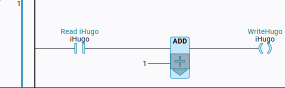 | The box indicates that the block has been selected. For example, for the Update Parameters command. The downward-pointing triangle allows the insertion of a new element parallel to the selected block. |

