Coffee Machine
The following application example illustrates the statechart of a coffee machine. It completely describes its process flow, determining how the machine behaves at runtime.
See the sample project UML_SC_CoffeeMachine.project in the installation subdirectory Projects.
Creating an application with a statechart
In CODESYS , create a new project with the Standard Project template. For PLC_PRG in, select the UML Statechart implementation language.
The project is created.
In the device tree, click the program
PLC_PRG.The editor consists of a window for the declaration and a window for the graphical implementation. In the ToolBox view, elements are listed which you can use to create a statechart.
Rename
PLC_PRGasCoffeeMachine.
Declaring variables for guard conditions
User input is mapped to Boolean variables which are usually set externally by a user via a user interface. When you assign the variable as a guard condition in the statechart, the flow logic becomes switchable. The variables act as control variables. A visualization as user interface is not described here.
PROGRAM CoffeeMachine
VAR
    bMakeCoffee : BOOL := FALSE;
    bShutDown : BOOL := FALSE;
    bPowerUp : BOOL := FALSE;
END_VAR
Implementing flow logic as a statechart
As long as no coffee is brewed, the coffee machine is in the state Idle. The request to make coffee gets the machine out of the idle state. Coffee brewing runs through the states Grind, Boil, Heat, Foam (milk) quasi-parallel in the orthogonal state CreateCoffee. Then the hot drink is brewed and served (Pour). Then the machine returns to the idle state.
The idle state is reached after power-on and the initialization phase Init. The machine is switched off from the idle state (Shutdown).
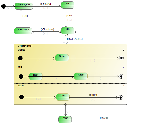
The state CreateCoffee is an orthogonal state that comprises multiple orthogonal regions. At runtime, the regions are executed quasi-parallel according to their priority. The statechart illustrates the term "orthogonal state".
In the device tree, double-click the program CoffeeMachine to open the editor and create the diagram illustrated above.
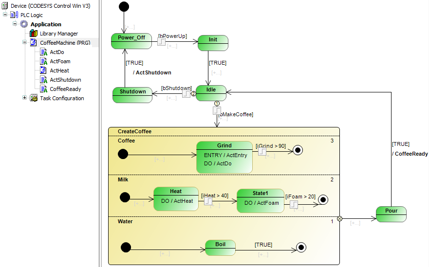
Adding methods and actions
When you have implemented the flow logic as a statechart, you add functionality to the states and transitions. In doing so, you add ENTRY, DO, and EXIT actions or methods for the states. You can also add an action or method to a transition, which is then called one time at the state transition.
Below you see the actions that have to be inserted below the statechart function block (program CoffeeMachine) for the coffee machine in the device tree. The code listed here is only placeholder code that will be extended later to evaluate I/Os mapped in variables, for example.
ActGrind
nGrind := nGrind + 10;
ActFoam
nFoam := nFoam + 5;;
ActFoam
nFoam := nFoam + 5;;
ActHeat
nFoam := nFoam + 5;;
ActShutdown
bShutDown := FALSE;
bPowerUp := FALSE;
CoffeeReady
bMakeCoffee := FALSE;
iGrind := 0;
iHeat := 20;
iFoam := 0;
Then assign the actions to the states and transitions as follows.
To add an action to a state, click one of the  ,
,  , or
, or  symbols. To add an action to a transition, click the
  symbol.