Simple State Machine
A simple state machine consists of states, transitions which control the state transition, and actions or methods. This allows you to design and implement the behavior of finite machines.
Creating an application with a statechart
Create a new project with the Standard Project template. For PLC_PRG in, select the UML Statechart implementation language.
The project is created.
In the device tree, select the application and click in the context menu.
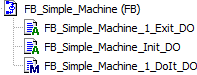
Create a function block named
FB_Simple_Machinein the UML Statechart (SC) implementation language.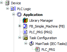
Instantiate the function block in the program
PLC_PRGand implement the call of the function block instance.PROGRAM PLC_PRG VAR fb_Simple_Machine_A : FB_Simple_Machine; END_VAR fb_Simple_Machine_A();Save the project as
SimpleMachine.project.
Designing flow logic as a statechart
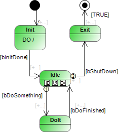
Example of requirements on the machine:
The machine is in the state
Idleafter the initialization phase.When events occur, the machine switches to the state
DoIt.When all actions and methods have been processed, the completion event is triggered and the machine returns to the idle state.
The machine can be switched from the idle state to the state
Exitand then to the end state.
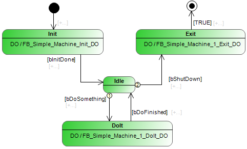
In this case, the design of the machine is as follows.
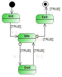
The design does not yet contain any guard conditions that control the flow logic. In addition, no actions or methods are called yet, so that the machine is still inoperative.
In the device tree, double-click the function block FB_Simple_Machine to open the editor and create the diagram illustrated above.
Declaring variables for guard conditions
PROGRAM FB_Simple_Machine
VAR
    bInitDone : BOOL := FALSE;
    bShutDown : BOOL := FALSE;
    bDoSomething : BOOL := FALSE;
    bDoFinished : BOOL := FALSE;
END_VAR
User input is mapped to Boolean variables which are usually set externally by a user via a user interface. When you assign the variable as a guard condition in the statechart, the flow logic becomes switchable. The variables act as control variables.
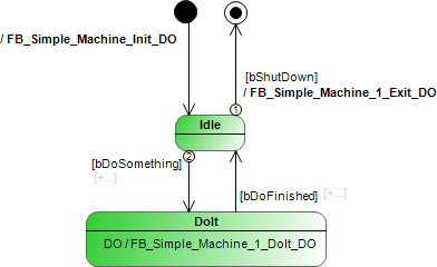
Adding methods and actions
When you have implemented the flow logic as a statechart, you add functionality to the states and transitions. In doing so, you extend the states with ENTRY, DO, and EXIT actions or methods. You can also add an action or method to a transition, which is then called one time at the state transition.
You can add actions to a state by selecting one of the  ,
,  , or
, or  symbols. You can click the
  symbol to add actions to a transition.
If you assign an action to transitions, then you can design a similar logic that differs only slightly in time behavior.
In the Devices view, you can trace the assignment of actions and methods. The actions and methods were created in the ST implementation language.