Statechart
A statechart is a graphical formalism with which you can graphically program a finite state machine. A state machine is a system that is continuously in one of a finite number of states at runtime. Actions can be executed in each state. When an event occurs, a transition to the next state takes place. Actions can also be performed during the transition.
In CODESYS, a statechart is a POU that is created in the Statechart implementation language. This type of POU is identified by the  symbol in the POUs view or Devices view. You can create programs, function blocks, functions, methods, actions, or properties as statecharts. The editor provides elements for states, pseudo states, and transitions.
States as well as transitions can call methods or actions. Pseudo states are control elements used to control the process, but they do not call any actions or methods.
 : State
 : Fast state
 : Composite state
 : Start state
 : End state
 : Fork/Join
 : Choice
 : Transition
 : Completion transition
 : Exception transition
A statechart has at least two states and two transitions to switch to the other state.
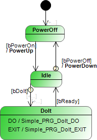
The guard condition of a transition that responds to an event is a Boolean expression or Boolean variable. It is displayed in regular font and in square brackets next to the transition line. Example below: [bPowerOn], [bPowerOff], [bDoIt], [bReady].
A transaction action is an action to be executed as soon as the guard condition of the transition is TRUE. The action name is displayed in bold font with // before the transition line.
Example below: //PowerUp //PowerDown TODO
Transitions have priorities that apply when the guard conditions of multiple outgoing transitions of the active state apply simultaneously. In this case, the priorities are represented in the diagram by a numeric symbol at the beginning of the transition line. See example below at the state Idle: (1) and (2).
States can have a total of three types of actions: ENTRY, DO, and EXIT. For details about these actions, see the help page for the State element.
The example shows the statechart for a simple machine with the usual three states: PowerOff, Idle, and DoIt. When an event occurs, which means that the created guard condition is fulfilled, the system switches to the next state. For example, the machine switches to the working status DoIt as soon as the guard condition bDoIt gets the value TRUE.
When all actions are ended, the machine switches back to the state Idle to wait for the next event. The machine can also be switched off (//PowerDown action) and is then in the PowerOff state.