Element: Realization
A Realization is a UML relationship which expresses instantiation. The realizing class object implements the attributes and operations of the interface. In IEC code, this relationship corresponds to the keyword IMPLEMENTS.
A realization points from a class (type: FUNCTION_BLOCK) to an interface.

Display as dashed arrow
Properties
Relationship | Relationship type |
Optimise route | When this option is selected, the route of the relationship arrow is optimized automatically. The fixed points are the initial point at the start element and the final point at the end element. For example, if the end element is moved, then the point where the arrow points to the end element remains the same. When this option is deselected, the route remains unchanged. As soon as a relationship element is positioned manually in the class diagram, this option is deselected. Select this option if automatic optimization is required. |
Start element | Name of the element where the relationship element starts |
End element | Name of the element that the relationship element points to |
Identifier | For the Association and Composition relationships only Name of the relationship element |
User input
Action | Description | |
|---|---|---|
| A realization is drawn between the elements. The IEC code is adapted automatically by specifying the interface in the declaration part of the class. Example: | |
| A new interface has been added. A realization is created that points from the class to the new interface. The IEC code is adapted automatically by specifying the interface in the declaration part of the class. Example: | |
| The lines are changed. The Optimise routing property is deselected automatically. | |
| The realization is removed from the diagram and IEC code. The statement | |


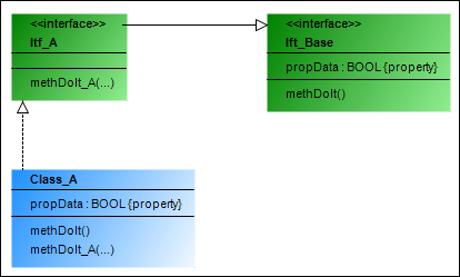
Example
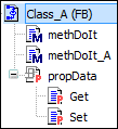
Class_A implements Itf_A:
View of Class_A in the POUs view: