Element: Association
An association is a UML relationship that expresses recognition. The recognizing element points to another element as a pointer.
In IEC code, this corresponds to a POINTER TO or REFERENCE TO statement (for example, ptrFb_A: POINTER TO Fb_A; or ptrFb_B: REFERENCE TO Fb_B;). That is why both Association (POINTER) and Association (REFERENCE) elements are available in the UML editor. The cardinality indicates how often the relationship occurs. In IEC code, this corresponds to an ARRAY[ .. ].
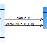
When you specify a cardinality greater than 1, the system declares the following:
ptrMulti_B : ARRAY[1..8] OF POINTER TO Fb_B;
An association points from a class or a global variable list to a class (type: FUNCTION_BLOCK) or a DUT.
Properties
Relationship | Relationship type |
Optimise route | When this option is selected, the route of the relationship arrow is optimized automatically. The fixed points are the initial point at the start element and the final point at the end element. For example, if the end element is moved, then the point where the arrow points to the end element remains the same. When this option is deselected, the route remains unchanged. As soon as a relationship element is positioned manually in the class diagram, this option is deselected. Select this option if automatic optimization is required. |
Start element | Name of the element where the relationship element starts |
End element | Name of the element that the relationship element points to |
Identifier | For the Association and Composition relationships only Name of the relationship element |
User input
Action | Description | |
|---|---|---|
| An association is drawn between the elements. The IEC code is adapted automatically by extending the declaration part of the existing element. Example: | |
| An association is created that points from the class or GVL to the new class. The IEC code is adapted automatically by extending the declaration part of the existing element. Example: | |
| The lines are changed. The Optimise routing property is deselected automatically. | |
| The association is removed from the diagram and IEC code. The | |


Examples
Fb_C recognizes Fb_B and Fb_A (single and multiple).
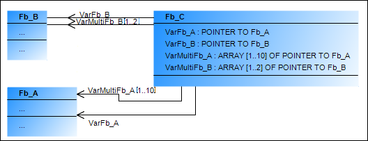
FUNCTION_BLOCK Fb_C
VAR
    VarFb_A : POINTER TO Fb_A;
    VarMultiFb_A: ARRAY [1..10] OF POINTER TO Fb_A; (* Kardinalität 10 *)
END_VARFb_C recognizes Dut_A.
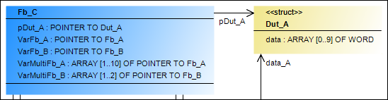
FUNCTION_BLOCK Fb_C
VAR
    pDut_A: POINTER TO Dut_A;
END_VARGVL recognizes POU_2.
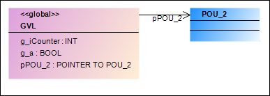
VAR_GLOBAL
    g_iCounter : INT;
    g_a : BOOL;
    pPOU_2: POINTER TO POU_2;
END_VAR