Preprocessing of Large G-Code Files
The CNC15_LargeGCode.project sample project is located in the installation directory of CODESYS under ..\CODESYS SoftMotion\Examples.
The sample project shows how to process large G-code files. Because very large files are especially common as output from CAD/CAM systems, this case is shown as an example.
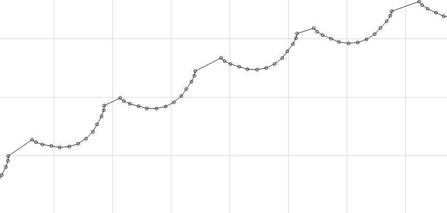
CAD/CAM systems often generate G-code files with several hundred thousand lines. These consist of very short linear segments (G1), typically in the range of 100 micrometers to one millimeter. These short linear segments trace the contour of the workpiece. They do not form a smooth path. The tangent usually jumps between the linear segments.
The example shows how to read these large files efficiently with constant memory requirements and how to achieve a smooth velocity curve on a path which consists of so many short linear segments. The original contour of the workpiece is reconstructed while preprocessing the G-code.
Structure of the application
The structure is typical for CNC applications. The G-code is read in the background task (PathTask), and path preprocessing also takes place here. The interpolation is performed in the bus task (MainTask).
Reading large files
In order to keep the latency at the beginning of the G-code processing short, a loop is used in the background task. For simplicity, a counter is used for the abort condition. Depending on the application, G-code, and PLC performance, other abort conditions such as a timer may be useful. The loop will end before reaching this abort condition when the path queue is full.
// Set this value depending on your other tasks, PLC performance, and G-Code
counter := 25;

WHILE counter > 0 AND
      (poqDataOut = 0 OR_ELSE (NOT poqDataOut^.bFull AND NOT poqDataOut^.bEndOfList))
DO
     <Read G-Code and process it>

     counter := counter - 1;
END_WHILE
By means of pipelining in the preprocessing, even very large G-code files can be read with small, constant memory requirements. The queue sizes are chosen to be large enough to allow the respective function blocks sufficient forecast.
The output queue of SMC_NCInterpreter is also the input queue of SMC_SmoothMerge. A total of 128+3 elements are reserved for the output queue. 3 is a reserve of the SMC_OutQueue and 128 remain for use as a forecast for SMC_SmoothMerge. SMC_SmoothMerge combines a maximum of 128 short linear segments into one spline.
The output queue of SMC_SmoothMerge is also the input queue of SMC_SmoothPath. SMC_SmoothPath requires at least 2 elements, plus a reserve of 3 elements, as a forecast. If M-functions are located between two smoothed elements, then more elements are required according to the number of M-functions.
The output queue of SMC_SmoothMerge is also the input queue of SMC_Interpolator. A forecast of 100 elements is suitable for most applications. For more information, see the following: Path Preprocessing and Queue Sizes.
/// Buffer of the interpreter, lookahead for SMC_SmoothMerge
aBufIp : ARRAY[0..130] OF SMC_GeoInfo;
/// Buffer of SMC_SmoothMerge
aBufSmm : ARRAY[0..15] OF SMC_GeoInfo;
/// Buffer of SMC_SmoothPath, lookahead for SMC_Interpolator
aBufSmp : ARRAY[0..99] OF SMC_GeoInfo;
Preprocessing of linear segments
The SMC_SmoothMerge function block ensures a smooth velocity curve on the many, very short linear segments. It combines as many consecutive linear segments as possible into one spline, while maintaining specified tolerances. In this example, a maximum deviation of 0.1 mm in X and Y is allowed (PARAMETERS.piMaxDifference).
Reading the short linear segments
Combining multiple linear segments into splines using
SMC_SmoothMerge.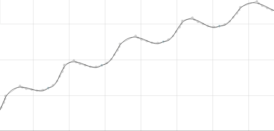
Smoothing between the splines with
SMC_SmoothPathbecause, as seen above, the splines do not connect tangentially to each other.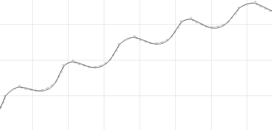
Commissioning
Build the application and download it to a controller.
Open the trace and download it to the controller.
Start the application.
You can track the processing of the G-code.