Using Depictor to Visualize Axis Groups
For this project, you also need the CODESYS Depictor add-on with a valid license.
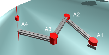
The SoftMotion application consists of four rotary drives configured as an axis group. The first three axes move the TCP in the X/Y-plane, and the fourth axis in the Z-plane.
The example demonstrates how you can use Depictor with the Kin_Scara3_Z kinematic configuration. You can also customize the same procedure for other kinematic configurations.
Creating the standard project
Create a standard project with the CODESYS SoftMotion Win controller and the ST programming language.
Add a Library Manager in the POUs view.
Open the Library Manager and add the libraries
SM3_DepictorandDepictorBase.
Adding and parameterizing the axes
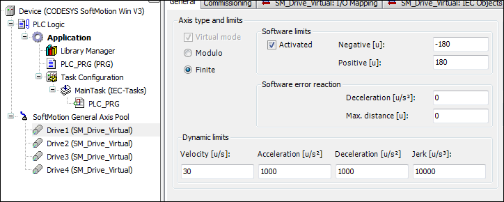
Insert four virtual axes below the object SoftMotion General Axis Pool and name the axes as Drive1...Drive4.
Parameterize the axes Drive1, Drive2, Drive3, and Drive4 as axis type finite with software limit switches from -180 degrees to 180 degrees.
Configuration editor:
For more information, see: Virtual Drive
Configuring the axis groups
Add a "KinScara" axis group below the application. To do this, click .
In the configurator, click Select kinematics. Select the TRAFO.Kin_Scara3_Z kinematics.
Define the parameters as follows:
dArmLength1, dArmLength2, dArmLength3: 500
dOffsetA1, dOffsetA2, dOffsetA3, dOffsetZ: 0
Order the axes as follows:
A1: Drive1
A2: Drive2
A3: Drive3
Z: Drive4
Note: You can drag the axes directly into the input field.
For more information, see: Kinematics
Creating the controller program
In the
PLC_PRGprogram, declare instances of theMC_Powerfunction block for all drives. Create anistatevariable for the statechart.VAR Power_Drive1, Power_Drive2, Power_Drive3, Power_Drive4 : MC_Power; istate: INT; END_VAR
Define a statechart in the implementation.
CASE istate OF
 0:
 1:
 2:
END_CASE
Activate all drives in state
0.0: Power_Drive1(Axis:=Drive1, Enable:=TRUE, bRegulatorOn:=TRUE, bDriveStart:=TRUE); Power_Drive2(Axis:=Drive2, Enable:=TRUE, bRegulatorOn:=TRUE, bDriveStart:=TRUE); Power_Drive3(Axis:=Drive3, Enable:=TRUE, bRegulatorOn:=TRUE, bDriveStart:=TRUE); Power_Drive4(Axis:=Drive4, Enable:=TRUE, bRegulatorOn:=TRUE, bDriveStart:=TRUE); IF Power_Drive1.Status AND Power_Drive2.Status AND Power_Drive3.Status AND Power_Drive4.Status THEN istate:=istate+1; END_IF
When the axes are activated, enable the axis group (switch from "deactivated" to "standby").
VAR
 GroupEnable:MC_GroupEnable;
END_VAR

1:
 GroupEnable(AxisGroup:=KinScara, Execute:=TRUE);
 IF GroupEnable.Done THEN
  istate:=istate+1;
 END_IF
Declare and initialize a variable to save the set value in machine coordinates. Declare two instances of type
SMC_POS_REFto represent the TCP in Cartesian and axis coordinates.VAR Frame: MC_COORD_REF:=(X:=-120, Y:=-25); // This variable stores the cartesian position & orientation of the TCP Pos_Cart: SMC_POS_REF; // This variable represents the position of the TCP in cartesian coordinates coordinates Pos_Axis: SMC_POS_REF := (a := axispos);// This variable represents the position of the TCP in Axis coordinates END_VAR VAR CONSTANT axispos: TRAFO.AXISPOS_REF := (a0 := 0, a1 := 100, a2:=60); END_VAR 2: Pos_Cart.c:= Frame; // To represent the TCP in cartesian coordinates;
Declare an instance of
MC_MoveDirectAbsoluteto move the SCARA robot to the specified coordinates.VAR MoveAbs:MC_MoveDirectAbsolute; // Moves the TCP to the defined coordinates END_VAR 2: MoveAbs(AxisGroup:=KinScara, Execute:=TRUE, Position:=Pos_Axis,CoordSystem:=SMC_COORD_SYSTEM.ACS, BufferMode:=MC_BUFFER_MODE.Aborting,); //move to the defined Axis coordinates //MoveAbs(AxisGroup:=KinScara, Execute:=TRUE, Position:=Pos_Cart,CoordSystem:=SMC_COORD_SYSTEM.MCS, BufferMode:=MC_BUFFER_MODE.Aborting,); //move to the defined cartesian coordinates IF MoveAbs.Done THEN MoveAbs(AxisGroup:=KinScara, Execute:=FALSE); // Waits for the next new coordinates istate:=2; END_IFDeclare a variable of type
SMC_GroupReadSetPositionto read the current value of the robot in Cartesian coordinates and axis coordinates.VAR Car_pos, Axis_pos :SMC_GroupReadSetPosition; //to read the current axis values END_VAR 2: Car_pos(AxisGroup:=KinScara, CoordSystem:=SM3_Robotics.SMC_COORD_SYSTEM.MCS, Enable:=TRUE); // to read the current position in cartesian coordinates Axis_pos(AxisGroup:=KinScara, CoordSystem:=SM3_Robotics.SMC_COORD_SYSTEM.ACS, Enable:=TRUE); // to read the current axis values
The entire PLC_PRG program
Compare your program and add the missing program parts.
Declaration
PROGRAM PLC_PRG
VAR
    Power_Drive1, Power_Drive2, Power_Drive3, Power_Drive4 :MC_Power;
    istate: INT;

    GroupEnable:MC_GroupEnable;

    Frame:MC_COORD_REF:=(X:=-120, Y:=-25); // This variable stores the cartesian position & orientation of the TCP
    Pos_Cart:SMC_POS_REF; // This variable represents the position of the TCP in cartesian coordinates coordinates
    Pos_Axis:SMC_POS_REF := (a := axispos);// This variable represents the position of the TCP in Axis coordinates

    MoveAbs:MC_MoveDirectAbsolute; // Moves the TCP to the defined coordinates (PTP)

    Car_pos,Axis_pos :SMC_GroupReadSetPosition; //to read the current position of the TCP in Cartesian and Axis Coordinates and display it on the visu

    scara_Config:trafo.Kin_Scara3_Z_Config; // To set the configuration of the SCARA_3_Z
    kin_Config:SMC_SetKinConfiguration; // To set the defined configuration of SCARA_3_Z to the axis group used
    nPeriod:DINT:=0; // SCARA_3_Z Period
    Xelbow:BOOL:=TRUE;

END_VAR
VAR CONSTANT
    axispos : TRAFO.AXISPOS_REF := (a0 := 0, a1 := 100, a2:=60);
END_VAR
Implementation
CASE istate OF

0:
 Power_Drive1(Axis:=Drive1, Enable:=TRUE, bRegulatorOn:=TRUE, bDriveStart:=TRUE);
 Power_Drive2(Axis:=Drive2, Enable:=TRUE, bRegulatorOn:=TRUE, bDriveStart:=TRUE);
 Power_Drive3(Axis:=Drive3, Enable:=TRUE, bRegulatorOn:=TRUE, bDriveStart:=TRUE);
 Power_Drive4(Axis:=Drive4, Enable:=TRUE, bRegulatorOn:=TRUE, bDriveStart:=TRUE);

 IF Power_Drive1.Status AND Power_Drive2.Status AND Power_Drive3.Status AND Power_Drive4.Status THEN
  istate:=istate+1;
 END_IF

1:
 GroupEnable(AxisGroup:=KinScara, Execute:=TRUE);

 IF GroupEnable.Done THEN
  istate:=istate+1;
 END_IF

2:
 scara_Config(xElbowRight:=Xelbow, nPeriodA3:=nPeriod);
 kin_Config(AxisGroup:=KinScara,ConfigData:=scara_Config.Config, Execute:=TRUE);
 Pos_Cart.c:=Frame; // To represent the TCP in cartesian coordinates

 Car_pos(AxisGroup:=KinScara, CoordSystem:=SM3_Robotics.SMC_COORD_SYSTEM.MCS, Enable:=TRUE); // read the current position in cartesian coordinates
 Axis_pos(AxisGroup:=KinScara, CoordSystem:=SM3_Robotics.SMC_COORD_SYSTEM.ACS, Enable:=TRUE); // read the current position in Axis coordinates

 MoveAbs(AxisGroup:=KinScara, Execute:=TRUE, Position:=Pos_Axis,CoordSystem:=SMC_COORD_SYSTEM.ACS, BufferMode:=MC_BUFFER_MODE.Aborting,); //move to the defined axis coordinates
 //MoveAbs(AxisGroup:=KinScara, Execute:=TRUE, Position:=Pos_Cart,CoordSystem:=SMC_COORD_SYSTEM.MCS, BufferMode:=MC_BUFFER_MODE.Aborting,); //move to the defined cartesian coordinates

 IF MoveAbs.Done THEN
  MoveAbs(AxisGroup:=KinScara, Execute:=FALSE); // Waits for the next new coordinates
  istate:=2;
 END_IF
END_CASE
Creating a Depictor program
Add a new "Depic" POU of "Program" type below the application. To do this, click .
Declare a variable of type
SM3_Depictor.SMC_R_Scara3_Z_Data. Declare a variableLrSizeof typeLREALand initialize the variable with the value of 100.VAR ScaraTrafo : SM3_Depictor.SMC_R_Scara3_Z_Data; LrSize:LREAL:=100; END_VAR
Insert a call to the function block in the implementation.
ScaraTrafo(AxisGroup:=KinScara, trf:=KinScara.trafo);
Add the "Depic" POU to the MainTask.
Configuring Depictor
Add a "Depictor" object below the application. To do this, click .
Double-click the object.
Select the Pose element in the Depictor tree.
Click .
The Box element is added below the pose.
Select the Depictor Ref. option in the properties of the element.
Click the
 button.
Select the SMC_R_Depictor_Scara3_Z object from the
SM3_Depictorlibrary.Define the interface variables as follows:
fb: Depic.ScaraTrafo
lrZ_: Drive1.fSetPosition
lrZmin: 10
lrZmax: -50
lrSize: Depic.LrSize
xShowPlane: 0
Creating visualizations
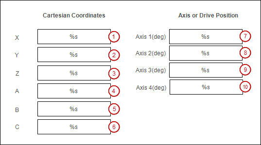
Create a visualization screen in which the Cartesian coordinates and the axis coordinates can be displayed and modified.
Add a "Visualization" object below the application. To do this, click .
Open the visualization in the editor.
Insert a Rectangle visualization element (1).
Change the properties of the element.
: %s
:
PLC_PRG.Car_pos.Position.c.XInput type: VisuDialogs.Numpad
Use another variable:
PLC_PRG.Frame.X
Insert the other Box visualization elements.
Change the properties of elements (2) and (3).
: %s
:
PLC_PRG.Car_pos.Position.c.YorPLC_PRG.Car_pos.Position.c.ZInput type: VisuDialogs.Numpad
Use another variable:
PLC_PRG.Frame.YandPLC_PRG.Frame.Z
Change the properties of elements (4), (5), and (6).
: %s
:
PLC_PRG.Frame.AorPLC_PRG.Frame.BorPLC_PRG.Frame.C
Change the properties of elements (7), (8), (9), and (10).
: %s
:
PLC_PRG.Axis_pos.Position.a.a0orPLC_PRG.Axis_pos.Position.a.a1orPLC_PRG.Axis_pos.Position.a.a2orPLC_PRG.Axis_pos.Position.a.a3Input type: VisuDialogs.Numpad
Use another variable:
PLC_PRG.Pos_Axis.a.a0andPLC_PRG.Pos_Axis.a.a1andPLC_PRG.Pos_Axis.a.a2andPLC_PRG.Pos_Axis.a.a3
Label the visualization elements with the Label element.
Starting and testing the program
You can modify the axis values in the visualization of the project. If you comment out the active movement command (MoveAbs..., ...) in the program PLC_PRG and remove the comments of the second movement command, then you can modify the Cartesian coordinates.
Build the project and download it to the PLC.
Open the editor of the Depictor object in your project.
Switch to the visualization and modify the axis values or the Cartesian values. Observe the movement of the SCARA robot in Depictor.