Custom Kinematics
See the CustomKinematics_Implementation.project sample project and the CustomKinematics.library library in the installation directory of CODESYS under ..\CODESYS SoftMotion\Examples.
This example describes how to create a library with a custom kinematic transformation (Gantry3C) and how to use this library in a project to control the robot.
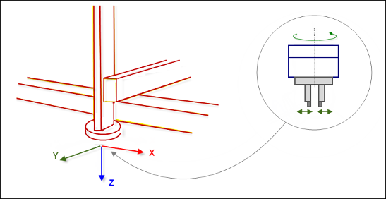
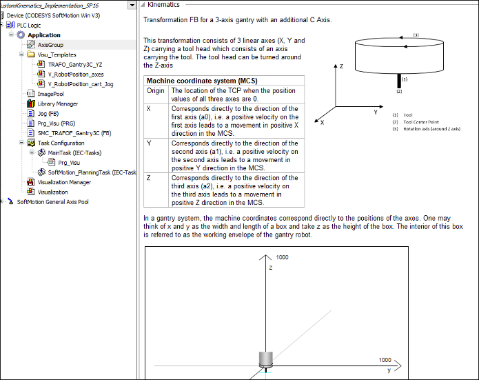
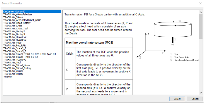
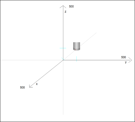
The Gantry3C kinematic transformation consists of 3 linear axes (X, Y, and Z) which carry a tool head. The tool head consists of an extra axis which carries a mounted tool. The tool head can be rotated around the Z-axis.
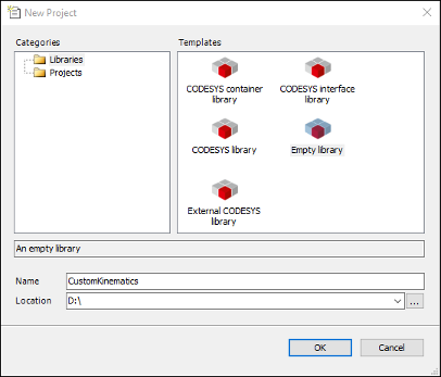
1. Create a new library project.
Create a new project with the Empty library template.
2. Add a Library Manager.
Add a Library Manager to the POUs view. Add the SM3_Transformation, SM3_Math, and SM3_Error libraries to the Library Manager.
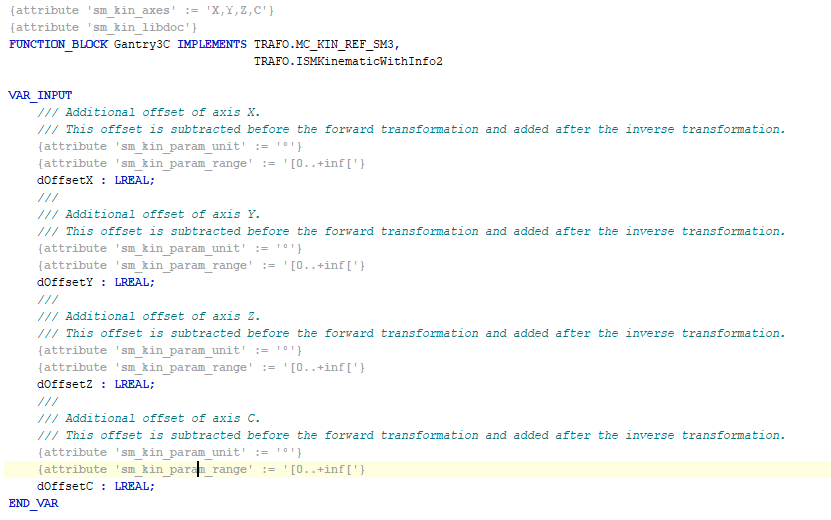
3. Create the Gantry3C function block.
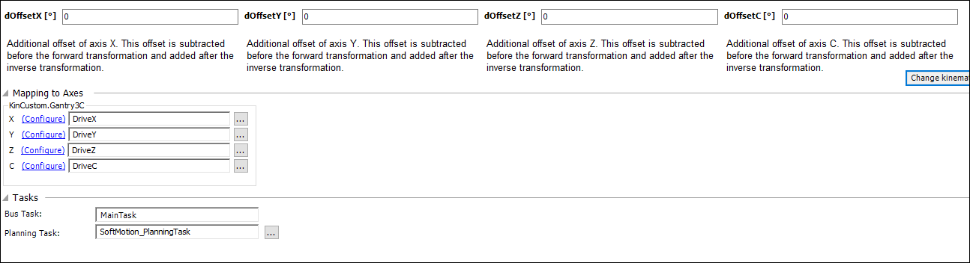
This function block implements the interfaces MC_KIN_REF_SM3 and ISMKinematicsWithInfo2 from the library SM3_Transformation. You can define an offset as input for each axis. This offset is subtracted before the forward transformation and added after the inverse transformation.
Example of Gantry3C with two decoupled kinematics and KinCoupled:
FUNCTION_BLOCK Custom_Kin_Gantry3 IMPLEMENTS ISMPositionKinematics
FUNCTION_BLOCK Custom_Kin_CAxis IMPLEMENTS ISMOrientationKinematics

FUNCTION_BLOCK Custom_Kin_Gantry3C EXTENDS Kin_Coupled
Provide the function blocks Custom_Kin_Gantry3 and Custom_Kin_CAxis as inputs for the Kin_Coupled function block during initialization. Now Custom_Kin_Gantry3C becomes a coupled kinematics combining the position and orientation kinematics.
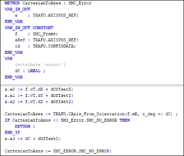
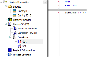
4. Implement the methods of the MC_KIN_REF_SM3 interface and the NumAxes4 property.
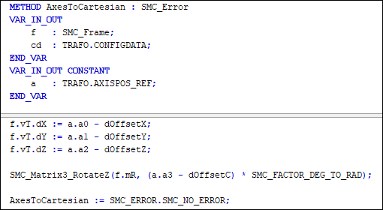
AxesToCartesian: Forward kinematics: Calculation of the position and orientation from the axis values.
CartesianToAxes: Inverse kinematics: Calculation of the axis values from position and orientation.
NumAxes: Number of axes of the kinematics
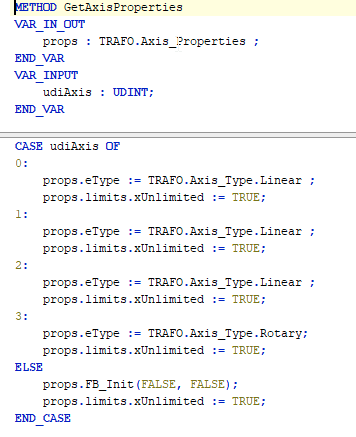
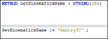
5. Implement the methods of the ISMKinematicsWithInfo2 and ISMKinematicsWithInfo interfaces.
GetAxisProperties: Properties, such as type of axis. The limits for each axis can be defined.
GetKinematicsName: Name of the kinematics
IsSingularity: Can be ignored for this kinematics
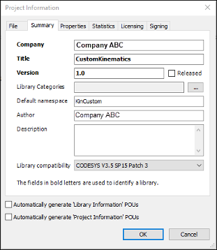
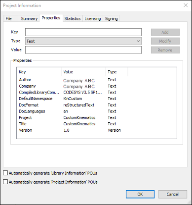
6. Specify the project information.
7. Check the library for compiler errors.
To check the library, click Build → Check all Pool Objects.
8. Create the description in the axis group configurator.
Important
To create the description, you first need to install the CODESYS Library Documentation Support add-on. This add-on contains the libdoc.exe program which is required in the following instructions.
The add-on can be installed via the CODESYS Installer.
When the POU has the attribute sm_kin_libdoc, the comment specified in the function block is used in the axis group configurator as a description of the kinematics. Restructured text formatting is used for this.
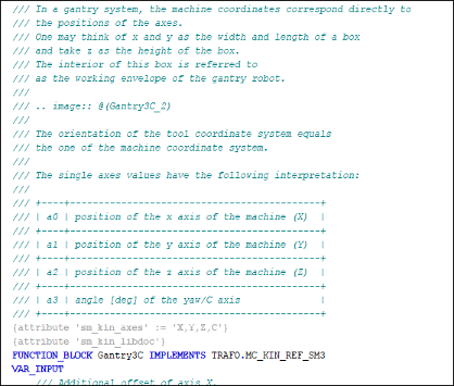
Include the attribute
sm_kin_libdocas shown in the image above.Include the required project properties DocFormat and DocLanguages (in the project information dialog) related to the library documentation.
Result:
Make sure that the installation directory of CODESYS contains the
libdoc.exeexecutable file (directory:...\DocScripting\3.5.xx.0\).Download the 32-bit wkhtmltox converter with version 0.12.5 or lower from https://wkhtmltopdf.org/downloads.html. Extract the
wkhtmltox.dllfile and copy it to...\DocScripting\3.5.xx.0\binin the CODESYS installation directory.Important
Since
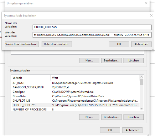
wkhtmltox.dllno longer supports images by default in Version 0.12.6 and higher, you need to use Version 0.12.5 or lower.Create the system variable
LIBDOC_CODESYSin Windows. Set the value to the file path ofCODESYS.exe. Make sure to specify the path name and the profile name in double quotation marks.Result:
Save, close, and reopen the library project.
Click the command.
The compiled library will be installed to the project which uses this kinematics.
Using the library in a project (CustomKinematics_Implementation.project)
The project demonstrates how to use and control the kinematics created in the previous section by jogging or commanding a movement.
Create a CODESYS standard project with the CODESYS SoftMotion Win controller.
Open the Library Manager and install the library
CustomKinematics.compiled-library(created in the previous section) containing the kinematics Gantry3C. Add the library to the Library Manager.Add an axis group object and select the KinCustom.Gantry3C kinematics.
Result:
Add 4 virtual axes to the SoftMotion General Axis Pool axis pool in the device tree. (DriveX, Y, Z, and C)
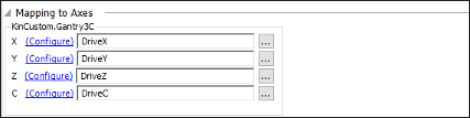
Open the axis group configurator. In the Mapping to Axes section, map the axes to their respective fields.
Result:
The program
Prg_Visuis the main program that controls the axis group. When the application is started,Prg_Visupowers up the axis group and enables it. Moreover, it calls all necessary function blocks to control the axis group (jogging, linear and PTP movements). All of these movements can be controlled from the attached visualization.Result:
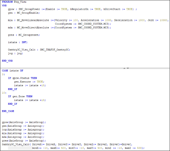
Function block:
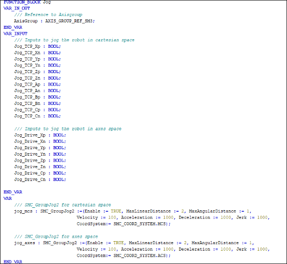
Jog: This FB combines jogging in axis space as well as in Cartesian space. It uses two instances ofSMC_GroupJog2. One is for axis space and the other is for Cartesian space. This function block can be used with the visualization templates V_RobotPosition_axes and V_RobotPosition_cart_Jog to jog any kinematics in Cartesian and axis space.Result:

FB SMC_TRAFOF_Gantry3C: This function block transforms the input axis values of a Gantry3C kinematics to its respective TCP values. In addition, the axis values are normalized so that they can be used with the visualization templateTRAFOF_Gantry3C_YZto visualize the movements of the kinematics.Result:
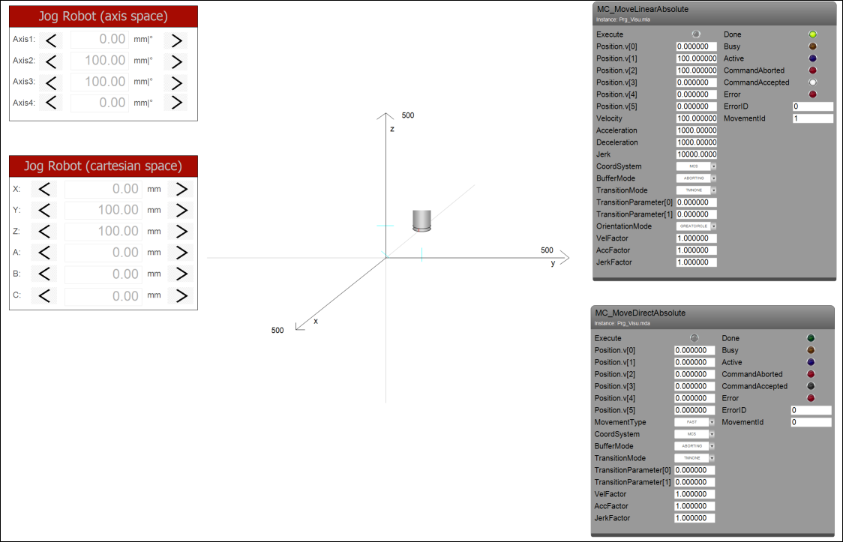
Compile and run the application. Open the visualization. You can jog the robot in axis space as well as in Cartesian space. There are also visualization templates to command a linear or a PTP movement.
Result:
Tip
The example described here discusses the positioning and orientation axes in a common function block. Many kinematics can comprise two decoupled partial kinematics: one positioning kinematic (delta, gantry, etc.) and one orientation kinematics (tools like C-axis, Wrist2, Wrist3, etc.). Both kinematics are connected to each other at the "flange point", the TCP of the positioning kinematics. The orientation kinematics is characterized by the fact that it is able to calculate the vector from the flange point to the TCP of the coupled kinematics. The calculation is done using only the orientation of this TCP (meaning that it is independent of the positioning kinematics or independent of the orientation of the flange point). The positioning kinematics in turn has to be able to determine its axis positions from only the position of the flange point. It must not depend on the orientation of the flange point.
In this case, you can resort to interfaces such as ISMPositionKinematics or ISMOrientationKinematics. To implement these interfaces, define one function block to implement ISMPositionKinematics and another function block to implement ISMOrientationKinematics. Finally, define a function block that extends the function block Kin_Coupled (from SM3_Transformation) with the previously defined function blocks as inputs.
For more information, see the following: Creating Custom Kinematics