Configuring a Tool Offset
You can set the offset between the flange coordinate system of the kinematics (XYZ) and the TCP coordinate system of the kinematics (X'Y'Z') by means of configuring a tool offset. This tool offset acts on all subsequent movements.
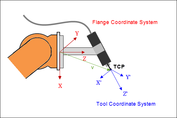
TCP: Tool Center Point
The tool offset is specified by a shift v=(x,y,z) and a rotation r=(A,B,C) in ZYZ Euler angles. Shift and rotation are expressed relative to the flange coordinate system of the kinematics.
When you configure a tool offset, it can be incompatible with the current kinematics. As a result, a tool offset can cause the kinematics to be incapable of achieving orientations. In this situation, an error is issued and the tool offset is ignored. For example, you can configure a tool offset in the Z-direction for the kinematics Kin_Scara2_Z. On the other hand, an offset with parts in the X- or Y-direction results in an error. When kinematics have these kinds of restrictions, they are described with the kinematics.
Function block: SMC_GroupSetTool
The function block configures the tool offset specified at the input ToolOffset (type MC_COORD_REF) for an axis group. However, as long as the axis group is in the state GroupDisabled or GroupErrorStop, no tool offset can be configured.
If the tool is not compatible with the current kinematics, then the POU issues the error SMC_AXIS_GROUP_TOOL_OFFSET_INCOMPATIBLE_WITH_KINEMATICS. This error is also issued if the interface ISMKinematicsWithOrientationImage has not been implemented for the kinematics description.
Function block: SMC_GroupReadTool
This function block reads the tool offset: output ToolOffset (type MC_COORD_REF). In this process, the ReadMode input determines whether the tool of the active movement, the last commanded movement, or the tool currently set in the axis group should be read.
Compatible kinematics
Not all kinematics support every tool offset. The following list shows which tools are suitable for which kinematics.
Kinematics | Compatible Tool |
|---|---|
SCARA 2 kinematics | Tools with position offset in the Z-direction and offset in the orientation |
SCARA 3 kinematics | All tools |
Polar kinematics | Tools with position offset in the Z-direction and offset in the orientation |
3-axis articulated robot | Tools with an offset in the orientation |
6-axis articulated robot | All tools |
4-axis palletizer | All tools |
Bipod | All tools |
5-axis gantry | All tools |
Gantry systems | All tools |
H-gantry system | All tools |
T-gantry system | All tools |
Rotary or linear tripod | All tools |
Tip
If a kinematic system does not have 3 degrees of freedom for the orientation, then it may be the case that not every tool offset is compatible.
For custom kinematics
In order to use your custom kinematics with a tool offset, you need to implement the ISMKinematicsWithOrientationImage interface. To add a tool offset for your custom position kinematics, you first have to implement the interface ISMPositionKinematics2.
Interface: ISMKinematicsWithOrientationImage
The kinematic interface provides the method GetFlangeOrientationImage with the variable mR_Flange of data type SMC_Matrix3, which contains the commanded orientation of the flange. As a consequence, the method returns possible resulting orientations oriInfo as data type OrientationSpace.
Behavior of the interface
In particular, when the orientation of the flange in the commanded orientation is known,
dof = zerois returned andmOriZerois set to the known orientation.If the orientation
Rof the flange is only partially known in the formR*vU = vRot(wherevUandvRotare known unit vectors), thendof = oneis returned.mOriZerois set to an orientation in the reachable space.Otherwise,
dof = threeis returned.
A specified tool offset is compatible with kinematics if the flange position can be calculated uniquely while taking the calculated orientation into account. This is always the case when the calculated orientation can be achieved by the kinematics. The tool offset may be incompatible only if not all orientations can be reached. Moreover, if the method GetFlangeOrientationImage returns dof = zero, then every tool offset is compatible. If the method returns dof = one, then only the tool position offset v_off parallel to the unit vector vU is compatible. In this case, R*v_off = R*vU*x = vRot*x does not depend on the unknown parts of the orientation matrix R. This also includes a tool offset with v_off = 0 (where x = 0). If dof = three is returned, then only position shifts without an offset in x/y/z are compatible.
Implementation notes
Implement the interface
ISMOrientationKinematicsWithOriImage2for orientation kinematics. Then a tool offset can be used for coupling the orientation kinematics with position kinematics. The interface has the methodGetOrientationImage2with the variableVAR_IN_OUT CONSTANT mR_Flangeof data typeSMC_Matrix3, which contains the commanded orientation of the flange.The method returns
csToolandoriinfowith the data typeOrientationSpacein the base coordinate system of the orientation kinematics.Moreover, the method returns in
bActivewhether the degrees of freedom fromorinfoare active (TRUE) or passive (FALSE).
Example of active degrees of freedom: Kin_CAxis. The rotation about the z-axis is controlled by the orientation kinematics axis.
Example of passive degrees of freedom: Kin_Wrist2. The remaining degree of freedom is the rotation of X/Y about the Z-axis, which points in the direction programmed by the user.
Important
When both the last commanded movement and the new movement are CP movements (both movements linear or rotary) during a tool change, the buffer mode of the subsequent movement is changed from Blending or Aborting to Buffered.
Important
If you configure a new tool offset after MC_GroupInterrupt and before MC_GroupContinue, then the old tool offset is used for the interrupted movements. The new tool offset is used only for movements that are commanded afterwards.
Important
When the kinematics are changed (MC_SetKinTransform), the tool offset is reset (no shift, no rotation).