Kinematic Configurations
A kinematic configuration describes the layout of the axes in an axis group to one another. Depending on the kinematics, several configurations are possible for the same TCP position.
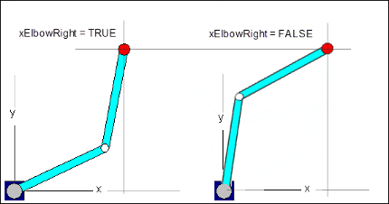
For example, two possible configurations are shown for SCARA 2.
The axis group has an active configuration that does not necessarily have to correspond to the current axis positions. If a movement is commanded, then the target position may be converted into axis coordinates. The configuration that is active at the time of commanding is used.
This active configuration can be set with the function block SMC_SetKinConfiguration. During initialization and each time the kinematics are changed, the axis group applies the standard configuration. All kinematics with a configuration has a standard configuration.
Tip
A CP movement between two configurations is not possible. In this case, the positioning has to be done by means of a PTP movement.
Tip
The current configuration can be determined with the function block MC_GroupReadActualPosition.
Setting the configuration for one kinematic design
Every kinematic design with a configuration has its own POU for calculating the configuration data. The name of this function block corresponds to the name of the kinematics plus the postfix _config. The POU converts the different configurations into the data type ConfigData. This data type is passed to the function block SMC_SetKinConfiguration.
Call the function block
Kin_Scara2_Z_Configfrom the librarySM3_Transformation. InputxElbowRight= TRUEThe function block yields the configuration data of type
ConfigData.Call the function block
SMC_SetKinConfigurationfrom the librarySM3_Robotics. Write the inputConfigDatawith the previously determined configuration data.Set the active configuration of the SCARA 2.
VAR
        config: TRAFO.Kin_Scara2_Z_Config;
        skc: SMC_SetKinConfiguration;
END_VAR

config(xElbowRight := TRUE);
skc(AxisGroup := Scara2, Execute := TRUE, ConfigData := config.Config);
Handling of coupled kinematics
Coupled kinematics exist when position kinematics and orientation kinematics are used simultaneously. This results in the "coupled" configuration from both configurations by calling Kin_Coupled_Config from the library SM3_Transformation. The configuration of the position kinematics and the orientation kinematics are provided to the function block at the inputs.
For more information, see: Rotary Axes with a Value Range over 360°