Tab: I/O Mapping
The variables that are used for the safety application to access the I/Os are defined on the I/O Mapping tab of the logical I/O device editor.
Tip
In CODESYS Safety Extension, I/O channels can be mapped to new variables only, not to existing variables.
Variables that are mapped to input channels contain the corresponding input signals from field devices and can thus be read. Variables that are mapped to output channels can be written and set output signals in field devices.
An implicit global variable with the corresponding name and the data type specified in the Type column are created in the safety application for each input or output channel of an I/O module that a variable has been assigned.
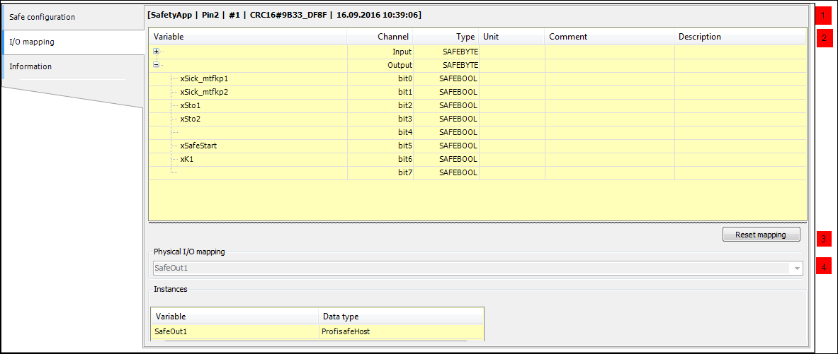
The top line (
 ) contains the pin information of the safety application, or In Work if the object version deviates from the pinned version, or if the safety application has not yet been pinned. For more information, see: Editor of the Safety Application Object
 : List of the variables of the I/O mapping with Variable (name), Channel (input and output), Data type, Unit, Comment, and Description
The information in the Channel, Data Type (IEC data type) , Unit, and Description columns is defined in the device description file and cannot be modified.
The Variable and Comment columns can be edited. If you specify a Comment for a logical exchange device, then the comment is displayed in the linked Logical Exchange GVL before the corresponding variable declaration.
 : Physical I/O: Display of the standard application object that is connected to this logical I/O
 : Instances: List of implicit instances. These are available to the safety application as global variables. For more information, see: Usage of the Logical I/Os
Important
Implicit code for a driver instance of the supported protocol type is created for each configured logical I/O. For more detailed information, see: Fieldbuses – General Part
SAFE data type (and the other way around) if the following requirements are fulfilled:It is an output channel.
A variable is already mapped to the channel or at least one of its subchannels.
Procedure: Click the cell of the data type of the superordinate channel to obtain a corresponding drop-down list.
If single bits of data type WORD or BYTE of the channel are mapped to Boolean variables for a logical exchange device, then you can activate an option for logical exchange in the connected GVL. This causes a variable with the corresponding combined data type WORD or BYTE to be used instead of the Boolean variable. For more detailed information, see: Logical Exchange GVL – Editor
Editing the mapping variables
The mapping variables are edited and displayed on the I/O Mapping tab of the logical I/O. To edit a variable, you must double-click the respective line to open it.
All mapping variables that are entered in the table are deleted when the Reset Mapping is clicked (the mapping of the physical device on the logical I/O is reset).
Specific displayed data types of an I/O channel can be converted to another data type. Converting the data types BOOL and SAFEBOOL is not possible. If you select the lines of the superordinate data type and click the data type, then a drop-down list opens. Depending on the device properties, the drop-down list contains one of the following possible selections:
BYTE,INT(unsigned short)SAFEBYTE,SAFEINT(unsigned short)WORD,DINT(unsigned int) and INT(signed)SAFEWORD,SAFEDINT(unsigned int) andSAFEINT(signed)DWORD,TIME(unsigned dint) andDINT(signed)SAFEDWORD,SAFETIME(unsigned dint) andSAFEDINT(signed)
The change of the data type means that the values of the variables are interpreted according to the data types in parentheses in the drop-down list. The channel width does not change by the conversion. By switching a channel between one numeric data type (e.g. SAFEINT) and a bit string data type (e.g. SAFEBYTE), mappable SAFEBOOL subchannels are removed or added depending on the data type and the device description.
Copy/cut and paste
You can exchange one or more lines with mapping entries by copying/cutting and pasting between the I/O Mapping tabs of different logical I/Os of the safety application. This applies for the variable names (Variable column) and the Comment. In this way, inserted variable names are made unique by adding a suffix (e.g. _1).
In addition, you can transfer mapping entries from the I/O Mapping tab to an Excel list by copy/cutting and pasting and also from an Excel list to the I/O Mapping tab. When entries are added to an Excel list on the I/O Mapping tab, only those entries are accepted in the columns that are editable in I/O Mapping (this means Variable and Comment). When copying from Excel, either complete mapping entries must be inserted (as they were copied from the tab), or entries from a single column can be inserted. In the second case, the contents selected in the Excel list are inserted in the selected column (Variable or Comment).
Tip
Changes on the I/O Mapping tab are marked in red. Only the last change is marked. All change markings are removed when the editor is closed.
For using the variables defined in I/O mapping in the project, see: Usage of Logical I/Os
Tip
If a device is assigned to the safety controller, then the mapping tab of the device editor shows only this assignment and no longer the channel mapping to the variables of the standard controller.
Tip
The editor of the logical I/Os of standard devices has no tab for safe configuration or safe device parameterization. The configuration and the device parameterization take place under the default application as in CODESYS Standard.