SF_MutingSeq
Tip
The version of the function block as described here corresponds to the latest version of the function block in Version list of function blocks.
Applicable safety standards
SF_MutingSeq is a certified PLCopen function block. For detailed information about applied standards, see "PLCopen – Technical Committee 5 – Safety Software".
Important
The requirements listed in the standards must be fulfilled by the user.
Interface description
Muting is the deliberate suppression of a safety function (example: light barrier). Sequential muting with four muting sensors is specified in this block.
Name | Data Type | Initial Value | Description, parameter values |
|---|---|---|---|
|
|
| |
|
|
| Variable
|
|
|
| Variable Status of muting sensor
Note: Depending on the safety requirements, |
|
|
| Variable. Status of muting sensor
Note: Depending on the safety requirements, |
|
|
| Variable. Status of muting sensor
Note: Depending on the safety requirements, |
|
|
| Variable Status of muting sensor
Note: Depending on the safety requirements, |
|
|
| Variable or constant. Shows the state of the muting lamp.
|
|
|
| Constant Maximum time for complete muting sequence, timer is started when the first muting sensor is actuated. The |
|
|
| Variable or constant. Command of the control system which activates the start of the muting function when required by the machine cycle. After starting the muting function, this signal can be switched off.
|
|
|
| |
|
|
|
MaxMutingTime
For developers in Extended Level: The MaxMutingTime input has to be set to a constant value. This means that this value must not be changed for the calls.
Name | Data Type | Initial Value | Description, parameter values |
|---|---|---|---|
|
|
| |
|
|
| Safety-oriented output, indicates the status of the non-isolating guard of the muting application.
|
|
|
| Displays the status of the muting process.
|
|
|
| |
|
|
|
Important
A short circuit in the muting sensor signals, or a functional application error in supporting these signals, is not supported by this function block, but is interpreted as an incorrect muting sequence. (Data type BOOL, supplied by the functional user hardware or software.) Nevertheless, this should not lead to unwanted muting. Users should consider this in their respective risk analyses.
Functional description
Muting is the deliberate suppression of a safety function. This is necessary, for example, when material is to be transported into the hazardous area without causing the machine to stop. Muting is triggered by a muting sensor. The use of two or four muting sensors and the correct integration into the production process has to ensure that no person enters the hazardous area while the light grid is muted. Muting sensors can be proximity switches, photoelectronic barriers, limit switches, etc. which do not have to be fail-safe. Active muting mode has to be indicated by indicator lamps.
There are sequential and parallel muting methods. Sequential muting with four muting sensors is used in this block. An execution of the forward direction of transport is listed below. The FB can be used in both directions: forward and backward. Muting should be activated by the MutingEnable signal from the process to prevent tampering. If the MutingEnable signal is not available, then the input has to be set to TRUE.
The input parameters of the function block include the signals of the four muting sensors (MutingSwitch11, MutingSwitch12, MutingSwitch21, and MutingSwitch22), as well as the OSSD signal of the "active opto-electronic protective device" S_AOPD_In.
Caution
The S_StartReset input shall only be activated if it is ensured that no hazardous situation can occur when the S-PLC is started.
No. | Image | Explanation |
|---|---|---|
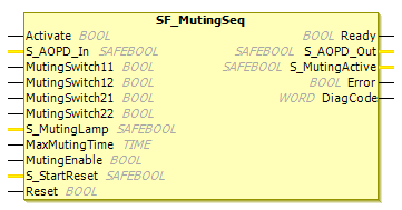
1 | 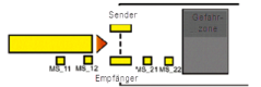 | If the muting sensor |
2 | 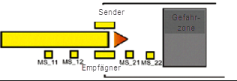 | Muting mode remains active as long as |
3 |  | Before the muting sensors |
4 | 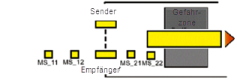 | Muting mode is ended when only muting sensor |
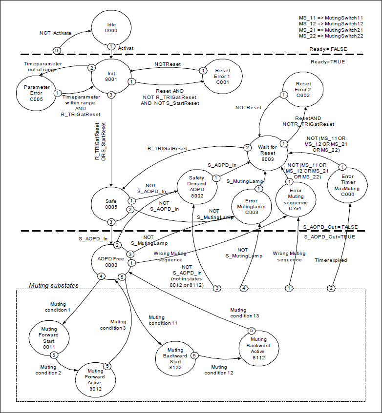
Status diagram
Tip
Note: The transition from any state to the Idle state, initiated by Activate = FALSE, is not shown. In every case, these transitions have the highest priority.
Typical timing diagram
SF_MutingSeq with S_StartReset = TRUE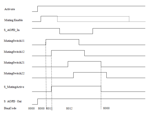
Muting conditions
Muting condition 1 (to status
16#8011) (MS_11is the first actuated input sensor). Start timer:MaxMutingTime:MutingEnable AND (R_TRIG at MS_11 AND NOT MS_12 AND NOT MS_21 AND NOT MS_22)Muting condition 2 (from status
16#8011to16#8012) (MS_12is the second actuated input sensor):MutingEnable AND (MS_11 AND R_TRIG at MS_12 AND NOT MS_21 AND NOT MS_22)Muting condition 3 (from status
16#8012to16#8000) (MS_21first actuated output sensor). Stop timer:MaxMutingTime:NOT MS_11 AND NOT MS_12 AND F_TRIG at MS_21 AND MS_22
Muting condition 11 (to status
16#8122) (MS_22is the first actuated input sensor). Start timer:MaxMutingTime:MutingEnable AND (NOT MS_11 AND NOT MS_12 AND NOT MS_21 AND R_TRIG at MS_22)Muting condition 12 (from status
16#8122to16#8112) (MS_21is the second actuated input sensor):MutingEnable AND (NOT MS_11 AND NOT MS_12 AND R_TRIG at MS_21 AND MS_22)Muting condition 13 (
MS_12the first actuated output sensor). Stop timer:MaxMutingTime:MS_11 AND F_TRIG at MS_12 AND NOT MS_21 AND NOT MS_22
In status
16#8000:(NOT MutingEnable AND R_TRIG at MS_11) OR (NOT MutingEnable AND R_TRIG at MS_22) OR (MS_12 OR MS_21) OR (MS_11 AND MS_22)In status
16#8011:NOT MutingEnable OR NOT MS_11 OR MS_21 OR MS_22In status
16#8012:R_TRIG at MS_11 OR R_TRIG at MS_12 OR F_TRIG at MS_22In status
16#8122:NOT MutingEnable OR MS_11 OR MS_12 OR NOT MS_22In status
16#8112:F_TRIG at MS_11 OR R_TRIG at MS_21 OR R_TRIG at MS_22
Error detection
The FB detects the following error conditions:
The muting sensors
MutingSwitch11,MutingSwitch12,MutingSwitch21, andMutingSwitch22are activated in the wrong order.Muting sequence starts without activation by
MutingEnable.A faulty muting lamp is indicated by
S_MutingLamp = FALSE.A static
Resetcondition.MaxMutingTimewas set to a value less than zero or greater thanT#10min.The muting function (
S_MutingActive = TRUE) exceeds the maximum muting timeMaxMutingTime.
Error behavior
In case of an error event, the outputs S_AOPD and S_MutingActive are set to FALSE. The DiagCode output displays the relevant error code and the Error output is set to TRUE.
A restart is prevented until the error conditions are clarified and the safe state is confirmed with Reset.
FB-specific error and status codes
| Statue Name | Status description and output setting |
|---|---|---|
|
| Static Reset condition detected after FB activation
|
|
| Static reset condition detected in status
|
|
| Error detected with muting lamp
|
|
| Error in muting sequence in status
|
|
|
|
|
| Timing error: Active muting time (if
|
| Statue Name | Status description and output setting |
|---|---|---|
|
| The function block is not active (basic state).
|
|
| Muting not active and no safety requirement from |
|
| The block has been activated.
|
|
| Safety request detected by
|
|
| Safety requirement or error was discovered and is now cleared. Confirmation
|
|
| Safety function activated
|
|
| Muting forward sequence is in the start phase, no safety requirement
|
|
| Muting forward sequence is active.
|
|
| Muting backward sequence is active.
|
|
| Muting backward sequence is in the start phase, no safety requirement
|