SF_TestableSafetySensor
Tip
The version of the function block as described here corresponds to the latest version of the function block in Version list of function blocks.
Applicable safety standards
SF_TestableSafetySensor is a certified PLCopen function block. For detailed information about applied standards, see "PLCopen – Technical Committee 5 – Safety Software".
Important
The requirements listed in the standards must be fulfilled by the user.
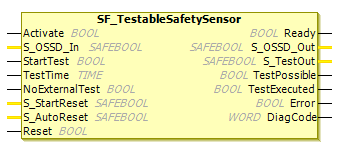
Interface description
This FB is used for periodic testing of a testable electronic/optical sensor or type 2 electro-sensitive protective equipment (ESPE). The FB can also be used for external testable safety sensors (ESPE: Electro-sensitive protective equipment, e.g. light beam). It also monitors the status of the safety sensor.
Name | Data Type | Initial Value | Description, parameter values |
|---|---|---|---|
|
|
| |
|
|
| Variable Status of the sensor output, e.g. light grid.
|
|
|
| Variable Input to start sensor test. Sets
|
|
|
| Constant. Range: Test time for safety sensor. The 'TestTime' caution note must be observed. |
|
|
| Constant Indicates whether external manual sensor test is supported.
|
|
|
| |
|
|
| |
|
|
|
TestTime
For developers in Extended Level: The TestTime input has to be set to a constant value. This value must not be changed for the calls.
Name | Data Type | Initial Value | Description, parameter values |
|---|---|---|---|
|
|
| |
|
|
| Safety-oriented output which displays the status of the ESPE.
|
|
|
| Coupled with the test input of the sensor. Although specified as
|
|
|
| Feedback signal to the process.
|
|
|
| A positive signal edge indicates successful execution of the automatic sensor test.
|
|
|
| |
|
|
|
Tip
OSSD stands for: Output Signal Switching Device
Functional description
Type 2 ESPE is used for periodic testing. It is intended to detect a hazardous error (for example, sensor failure, response time exceeds the specified time). The test signal should simulate the operation of the measurement control and the duration of the periodic test should not exceed 150 ms. The test should verify that each light beam operates in the manner specified by the user. If the test should be initiated by an external, safety-oriented control system (e.g. a machine), then the ESPE should be equipped with suitable input equipment (e.g. terminal).
Important
The ESPE has to be selected according to the product standards and the required categories according to the standards.
It has to be monitored with a separate functionality that the test is initiated within appropriate intervals.
Caution
The S_StartReset and S_AutoReset inputs shall only be activated if it is ensured that no hazardous situation can arise when the S-PLC is started.
StartTest = TRUE:STestOut = FALSE. Start of the monitoring timeS_TestOutsignal stops the transmitter (monitoring ofTestTimestarted for the first time)S_OSSD_Inswitches fromTRUEtoFALSE(monitoring ofTestTimestarted for the second time)S_TestOutswitches fromFALSEtoTRUEStart transmitter
Sensor
S_OSSD_Inswitches fromFALSEtoTRUEStop monitoring time
S_OSSD_OutisTRUEduring the test
Startup lock after activation of the FB
Startup lock after interruption of the guard
Status diagram
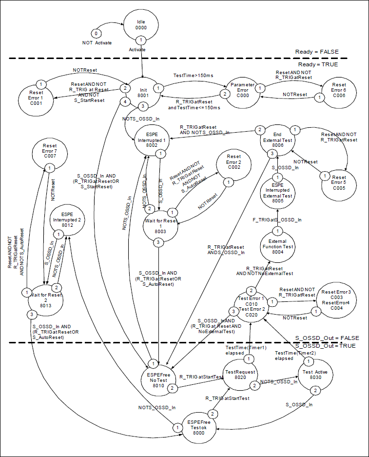
Tip
Note: The transition from any state to the Idle state, initiated by Activate = FALSE, is not shown. In every case, these transitions have the highest priority.
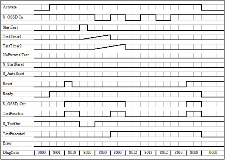
Timing diagram
Error detection
The following conditions force a transition to error status:
Test timeout without delayed sensor feedback
Test without sensor signal feedback
Invalid static Reset signal in the process
Plausibility check of the monitoring time setting
Error behavior
In case of an error event, the S_OSSD_Out output is set to FALSE and remains in this state. As soon as the error has been corrected and the sensor is in operation (S_OSSD_In = TRUE), a reset removes the error status and sets the S_OSSD_Out output to TRUE.
If S_AutoReset = FALSE, then a rising trigger edge is required at Reset.
After the transition from S_OSSD_In to TRUE, the optional startup lock can be restarted by a rising edge at the Reset input.
After function block activation, the optional startup lock can be restarted by a rising trigger edge at the Reset input.
FB-Specific Error and Status Codes
| Statue Name | Status description and output setting |
|---|---|---|
|
| Invalid value of the TestTime parameter Values between
|
|
| Static Reset condition detected after FB activation
|
|
| Static
|
|
| Static reset condition detected in status
|
|
| Static reset condition detected in status
|
|
| Static reset condition detected in status
|
|
| Static reset condition detected in status
|
|
| Static reset condition detected in status
|
|
| Test time expired in status
|
|
| Test time expired in status
|
| Statue Name | Status description and output setting |
|---|---|---|
|
| The function block is not active (basic state).
|
|
| An activation was detected by the function block.
|
|
| The FB has detected a safety requirement. The switch has not yet been tested automatically.
|
|
| Wait for rising trigger edge after status
|
|
| The automatic sensor test has failed. An external manual sensor test is necessary. Support for the necessary external manual sensor test has been activated on the function block ( A negative signal edge is required at the sensor.
|
|
| The automatic sensor test has failed. An external manual sensor test is necessary. Support for the necessary external manual sensor test has been activated on the function block ( A
|
|
| The automatic sensor test has failed. An external manual sensor test is necessary. Support for the necessary external manual sensor test has been activated on the function block ( The external manual test is complete. The device detected a complete sensor switching cycle (externally controlled).
|
|
| The FB has not detected a safety requirement. The sensor was not tested automatically.
|
|
| The automatic sensor test is active. Test Timer is started for the first time. The transmitter signal has been switched off by the function block. The signal of the receiver has to follow the signal of the transmitter.
|
|
| The automatic sensor test is active. Test Timer is started for the second time. The transmitter signal of the sensor has been switched on by the function block. The signal of the receiver has to follow the signal of the transmitter.
|
|
| The FB has not detected a safety requirement. The sensor was tested automatically.
|
|
| The FB has detected a safety requirement. The switch was tested automatically.
|
|
| Wait for a rising trigger edge of Reset after status
|