General Rules for Safety-Related Function Blocks
These programming rules correspond to the "General Rules for Safety-Related Function Blocks" of the PLCopen. This applies to PLCopen-compliant function blocks.
Guidelines specific to function blocks
Important
PLCopen FBs can be used only in programs and function blocks where "Single call" is set.
Default signal | All safety-oriented Boolean I/O signals have the preset safe value |
Signal level | The value
This reflects the functionality of IEC 61131 environments, such as the rules for the default value and that all outputs are set to |
Outputs | Every output must be assigned in each cycle. |
Missing I/O parameters | Missing parameters are permitted. The default values apply. These default values should in under no condition lead to an unsafe state. The default values and their attributes ( |
Startup behavior | At the start, the outputs are set to default values. After the first FB call, the outputs are valid. There is a consistent startup behavior (cold start). |
Timing diagram | Timing diagrams as shown for the function blocks are used for explanation only. They do not represent the exact time behavior. The exact time behavior depends on the implementation. |
Error handling and diagnosis | All safety-oriented function blocks have two error-related outputs: The provision for safety-oriented environments is that the activation of the safety-oriented function has the highest priority and that there is sufficient time for diagnosis in the subsequent activation, either in the functional program or in the user interface. |
General input parameters
Name | Data Type | Description |
|---|---|---|
|
| Variable or constant for the activation of the FB Initial value: This parameter can be linked to the variables that represent the state (active or not active) of the relevant safety device. This guarantees that no irrelevant diagnosis data is generated when the device is deactivated.
If no device is connected, then a static |
|
| Every name of an input of Only variables can be assigned. |
|
| Variable or constant Activation of the automatic start of the POU when the S-PLC is started (warm or cold).
The Safety notes for |
|
| Variable or constant Activation of the automatic restart of the POU
The Safety notes for |
|
| Variable Initial value: Depending on the function, this input can be used for different purposes.
This function is active only for a signal switch from The Safety notes for The applicable meaning is described for each POU. |
Safety notes for S_StartReset
S_StartReset
This automatic start should be activated only if it is guaranteed that no hazard can occur when starting the S-PLC. Therefore, the use of the feature "automatic start" of the function blocks requires to implement other system or application measures for making sure that no unexpected (or unintentional) startup occurs.
Caution
If the input is linked to a variable (and not to FALSE), then additional validation measures must be defined for it.
Safety notes for S_AutoReset
Caution
The automatic restart should be activated only if is it guaranteed that there can be no possible restart of the machinery after releasing the emergency stop button. Therefore, the use of the feature "automatic restart" of the function blocks requires to implement other system or application measures for making sure that no unexpected (or unintentional) restart of the machinery occurs.
Caution
If the input is linked to a variable (and not to FALSE), then additional validation measures must be defined for it.
Safety notes for Reset
Caution
Depending on the safety requirements, SAFEBOOL must be connected instead of BOOL.
General output parameters
Name | Data Type | Description |
|---|---|---|
|
|
|
|
| Every name of a |
|
| Error flag (same as the "K1/K2" LED of a safety relay).
This is useful in debug mode, as well as for further processing in the functional program. |
|
| Diagnosis registry. All POU states ( This is useful in debug mode, as well as for further processing in the functional program. |
Diagnostic codes
A transparent and uniform diagnosis concept creates the basis for all blocks. This makes sure that uniform diagnostic information is available to end users in the form of DiagCode, regardless of the implementation of the end user. If there are no errors, then the internal state of the block (state machine) is displayed. Any errors are displayed via a binary output (Error) For more detailed information about internal or external block errors, see DiagCode. The block must be reset by means of various Reset inputs.
| Description |
|---|---|
| The POU is not activated or the safety CPU is halted. |
| Indicates that the activated POU is in operating state without errors.
|
| Indicates that the activated POU is in error state.
|
| Description |
|---|---|
|
Note: |
| Description |
|---|---|
| The POU is not activated. This code represents the idle state. As a general example, the I/O setting could be as follows:
|
| The function block is activated without errors or other conditions that set the safety output to
|
| An activation was detected by the block and the block is now activated. However, the
|
| The activated POU detects a safety demand (example:
|
| The safety output of the active POU has been deactivated by a safety request. The safety request is now canceled, but the safety output remains
|
Generic state chart
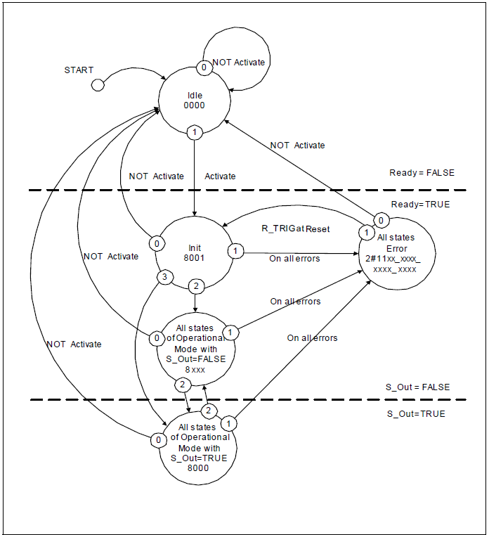
It provides a general overview of the states and transitions. Some transitions are not named, which means that they are FB-specific and must be assigned with the respective FB.
The diagram shows three areas:
In the top area, the function block is not active and in the safe state (safe outputs are
FALSE).In the middle area, the function block is active and in the safe state (safe outputs are
FALSE).In the bottom area, the function block is in the normal state (safe outputs are
TRUE).
The first horizontal line in the status diagram shows the transition from an inactive FB to an active FB.
The second horizontal line shows the transition from a unsafe state to a safe state.
The priorities of possible parallel transitions are given by numbers (highest priority
0).The states contain the state name and the hexadecimal diagnostic code.
The conditions
OR,AND, andXORare used as logical operators andNOTas negation.In the FB description, the start state is
Idle, with the transitions to the individual operating states via theInitstate.Activate=FALSEswitches from each state directly to theIdlestate (0= highest priority is reserved forActivate=FALSE). For improved overview, these transitions are not shown in each status diagram. This is mentioned as a footnote in each status diagram.Dur to the overview, the setting of outputs is not defined in the state chart. An explicit truth table, which includes the information "FB states to output (outputs) ", is part of each FB specification with the FB-specific error and stats codes.
| Status Name | Status description and output setting |
|---|---|---|
|
|
|
| Status Name | Status description and output setting |
|---|---|---|
|
|
|
|
|
|
| All states of the operating mode where |
|
| All states of the operating mode where |
|