SF_EDM (External Device Monitoring)
Tip
The version of the function block as described here corresponds to the latest version of the function block in Version list of function blocks.
Applicable safety standards
SF_EDM is a certified PLCopen function block. For detailed information about applied standards, see "PLCopen – Technical Committee 5 – Safety Software".
Important
The requirements listed in the standards must be fulfilled by the user.
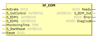
Interface description
This function block applies an input signal (S_OutControl) to an output signal (S_EDM_Out). The function block monitors that two inputs switch off within a defined time (MonitoringTime). If they do not switch off within the defined time, S_EDM_OUT is set to FALSE.
The SF_EDM (External Device Monitoring) FB monitors the initial state and the switching state of actuators, for example switch amplifiers, which are controlled by safe output devices.
Name | Data Type | Initial Value | Description, parameter values |
|---|---|---|---|
|
|
| |
|
|
| Variable. Control signal of the preceding safety FBs. Typical function block signals from the PLCopen library (e.g.
|
|
|
| Variable. Feedback signal of the first connected actuator (switch amplifier).
|
|
|
| Variable Feedback signal of the second connected actuator (switch amplifier). If only one signal is used in the application, then the user must use a graphic connection to jumper the
|
|
|
| Constant. Maximum response time of the connected and monitored actuators. The MonitoringTime caution note must be observed. |
|
|
| |
|
|
|
MonitoringTime
For developers in Extended Level: The MonitoringTime input has to be set to a constant value. This means that the value must not be changed for the calls.
Name | Data Type | Initial Value | Description, parameter values |
|---|---|---|---|
|
|
| |
|
|
| Controls the actuator. The result is monitored by the feedback signal
|
|
|
| |
|
|
|
Functional description
The SF_EDM FB controls a safety output and monitors controlled actuators.
This function block monitors the initial state of the actuators via the feedback signals (S_EDM1 and S_EDM2) before the actuators are enabled by the FB.
The function block monitors the switching state of the actuators (MonitoringTime) after the actuators have been enabled by the FB.
Two single feedback signals must be used for an exact diagnosis of the connected actuators. A common feedback signal from the two connected actuators must be used for a restricted yet simple diagnostic function of the connected actuators. In this case, the user must connect this common signal to both S_EDM1 and S_EDM2 parameters. S_EDM1 and S_EDM2 are then controlled by the same signal.
The switching devices used in the safety function should be selected from the category specified in the risk analysis.
Optional startup lock:
Startup lock in the event of block activation
Caution
The S_StartReset input shall only be activated if it is ensured that no hazardous situation can occur when the S-PLC is started.
Status diagram
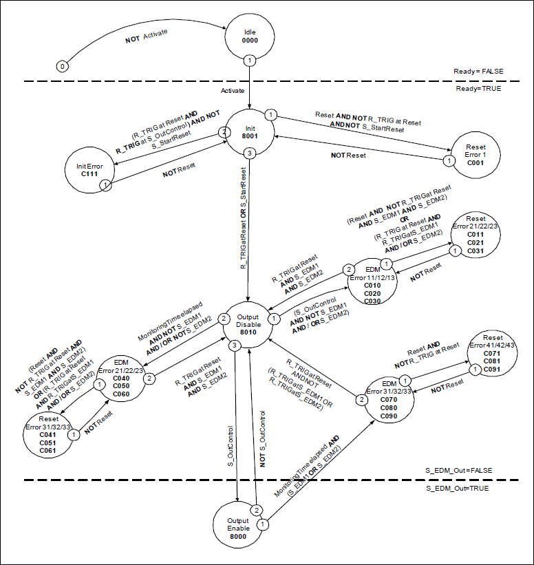
Tip
Note: The transition from any state to the Idle state, initiated by Activate = FALSE, is not shown. In every case, these transitions have the highest priority.
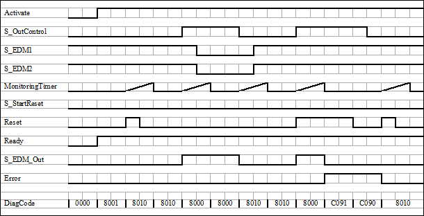
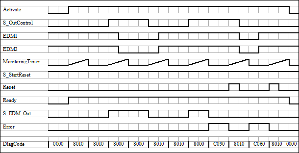
Typical timing diagrams
Error detection
The following conditions force a transition to the Error state:
Invalid static
Resetsignal in the processInvalid
EDMsignal in the processThe
S_OutControlandResetinputs are incorrectly interconnected due to programming error.
Error behavior
In error states, the outputs are as follows:
The
S_EDM_Outis set toFALSEand remains in this safe state.An
EDMerror message must always be reset by a rising trigger at Reset.A Reset error message can be reset by setting Reset to
FALSE.
After function block activation, the optional startup inhibit can be reset by a rising edge at the Reset input.
FB-Specific Error and Status Codes
DiagCode | Statue Name | Status description and output setting |
|---|---|---|
|
| Static
|
|
| Static
|
|
| Static
|
|
| Static
|
|
| Static
|
|
| Static
|
|
| Static
|
|
| Static
|
|
| Static
|
|
| Static
|
|
| The signal at
|
|
| The signal at
|
|
| The signals at
|
|
| The signal at
|
|
| The signal at
|
|
| The signals at
|
|
| The signal at
|
|
| The signal at Ready = TRUE S_EDM_Out = FALSE Error = TRUE |
|
| The signals at
|
|
| Similar signals at
|
| Statue Name | Status description and output setting |
|---|---|---|
|
| The function block is not active (basic state).
|
|
| Block activation startup lock is active. Reset required.
|
|
| EDM control is not active. Timer starts when state is entered.
|
|
| EDM control is active. Timer starts when state is entered.
|