Synchronizing Redundant Data
Basically, you can use the redundancy area type to influence whether and when the redundancy data is synchronized and from where to where the data is copied.
When the Redundancy Configuration object exists in the application, the AREA_INPUT redundancy area type is assigned by default to all variables (in all global variable lists and all programs which the user creates). This also happens if you add the object to the application later. As a result, all variables are registered by default.
A list of these objects is located in the Redundancy Configuration editor on the Registered Areas tab.
For more information, see: General
Synchronization when starting the redundancy system
When the second PLC is started, the redundancy data (with AREA_INPUT redundancy area type) is copied first and one time from the active PLC to the second PLC. Then the PLC switches to standby.
However, you can deselect the default AREA_INPUT redundancy area type to exclude variables from the synchronization.
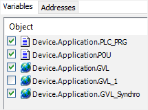
In the Redundancy Configuration editor, on the Registered Areas tab, click the Variables tab.
A list of objects (type Program or Global Variable List) is displayed below Object. The activated objects are selected for the synchronization and therefore get the
AREA_INPUTredundancy area type.Deactivate an object.
Example
Tip
This is advisable for local diagnosis data of the fieldbus or for a local redundancy state.
Synchronizing in every task cycle
When the configuration file of the runtime system (*.cfg) contains the following entry, a synchronization is triggered every time a task cycle is started.
[CmpRedundancy]
DataSyncAlways=1
The variables of PROGRAM objects and global variable lists whose redundancy area type is AREA_INPUT are affected.
PROGRAM PLC_PRG
VAR
    b: INT;
END_VAR

IF sReduState.eRedundancyState = RDCY.STATE.RS_CYCLE_ACTIVE THEN
    b := b + 1;
END_IF
The b variable is incremented only in the active PLC. Because data in the redundancy system is synchronized with each task cycle, the redundancy variable is continuously transferred to the second PLC.
Synchronizing on demand
If the configuration file of the runtime system (<rts name>.cfg) does not contain the entry DataSyncAlways=1, it may be preferable to trigger a synchronization programmatically in the IEC code.
To do this, call the RedundancySynchronizeData() function in your IEC code. Then the variables with the AREA_INPUT redundancy area type are synchronized. Therefore, check the settings on the Registered Area tab on the Variables tab. The copy operation is performed at the beginning of the task cycle.
In active/standby mode, the b variable is incremented in the active PLC. When bUpdateData is set, a data synchronization is triggered one time and the value is transferred to the second PLC.
IF bUpdateData THEN
    bUpdateData := FALSE;
    RedundancySynchronizeData();
END_IF
Synchronizing from the active PLC to the standby PLC in every task cycle
The AREA_SYNCHRO redundancy data of type can be transferred during operation in each task cycle from the active PLC to the standby PLC. The size of the data is limited for this. The assignment of the type is not supported in CODESYS, but has to be done programmatically as a callback of the AreaRegister function.
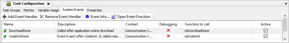
The area has to be registered before the application starts. It is too late to register areas in the first cycle. That is why the registration is done in the callback of the cbDownloadDone system event.
FUNCTION cbDownloadDone : DWORD
VAR_IN_OUT
        EventPrm: CmpApp.EVTPARAM_CmpApp;
END_VAR

(* Register GVL_Synchro to be synchronized in every task cycle *)
bAreaRegisterDone := AreaRegister(ADR(iSyncFirst), ADR(iSyncLast) - ADR(iSyncFirst) + sizeof(iSyncLast), AREA_TYPE.AREA_SYNCHRO);
tNowDownloadDone := TIME();
The call of cbDownloadDone is performed when the OnlineChangeDone system event occurs. System events are added to the task configuration.
Tip
Note that the AreaRegister function is hidden in some versions of the redundancy library but can still be called.
Synchronizing from the standby PLC to the active PLC in every task cycle
The AREA_PASSIVE redundancy data of type can be transferred during operation in each task cycle from the standby PLC to the active PLC. The size of the data is limited for this. The assignment of the type is not supported in CODESYS, but has to be done programmatically as a callback of the AreaRegister function.
The area has to be registered before the application starts. It is too late to register areas in the first cycle. As a result, the registration is done in the callback of the cbDownloadDone system event (in the same way as in the example from the previous chapter).
FUNCTION cbDownloadDone : DWORD
VAR_IN_OUT
    EventPrm: CmpApp.EVTPARAM_CmpApp;
END_VAR

(* Register GVL_Synchro to be synchronized in every task cycle *)
bAreaRegisterDone := AreaRegister(ADR(iSyncFirst), ADR(iSyncLast) - ADR(iSyncFirst) + sizeof(iSyncLast), AREA_TYPE.AREA_PASSIVE);
tNowDownloadDone := TIME();
The call of cbDownloadDone is performed when the OnlineChangeDone system event occurs. System events are added to the task configuration.
Synchronizing the timer
The value of the IEC time base is transferred from the active PLC to the standby PLC in every PLC cycle. This affects TIME, TON, and TOF. The system times (example: SysTimeGetMs) are not transferred and are available as a local time on each PLC.
Setting the timeout for the synchronization of registered areas
To set a suitable value for the Synchronization timeout of registered areas in the Redundancy Settings, you can first determine this using a system trace:
In the device tree, add a Trace object below the device object.
In the Redundancy Settings on the General tab, select the Record the needed sync time in system trace option.
Load and start the trace recording of the system trace.
The default value of the timeout during synchronization
SyncWaitTimeis the value ofStandbyWaitTime, which in turn is preset to a value of 30ms.If the set
SyncWaitTimeis too short, then the following message is displayed in the log: "Synchronization terminated after %" PRI_UI32 "ms because of SyncWaitTime".When the set SyncWaitTime is long enough, the SyncTime actually required is recorded in the system trace. You can try to optimize the set
SyncWaitTimeso that it comes as close as possible to the SyncTime actually required.