Tab: Redundancy Settings: Visualization
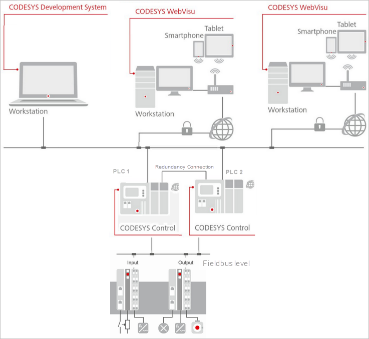
The tab contains the configuration for the connection from one ore more CODESYS WebVisu clients to a redundant control system with two PLCs.
If at runtime the active PLC fails, then the execution of the control application is taken over by the PLC previously in standby mode. The switching process takes place smoothly and therefore almost unnoticed by the connected visualization clients.
Tip
Similar configurations are also possible based on a CODESYS HMI when these are run redundantly.
 |
Read | Reads into the dialog the current settings of the redundancy link for PLC 1 |
Write | Transfers the available settings of the redundancy link on both devices |
Switchover references
Important
To use the following functions, the following is required:
At least version V4.9.0.0 of the CODESYS Visualization add-on.
At least V4.3.0.0 of the CODESYS Redundancy Configuration add-on is required.
Enable |
The task configuration is extended with the IEC task The Switchover references input field is available for the communication settings. |

Switchover IP addresses | List of configured switchover IP addresses ImportantThe IP addresses or host names for communication switching in the web visualization can be configured on this tab. When switching from PLC 1 to PLC 2, the addresses entered here are used. |
PLC 1 | List of IP addresses for PLC 1 |
PLC 2 | List of IP addresses for PLC 2 |
Webvisu port on PLC 1 | Port used by the visualization clients of PLC 1 Default: The port determines how the web visualization clients connect to the PLC. |
Webvisu port on PLC 2 | Port used by the visualization clients of PLC 2 Default: |
Add | The Add Switchover Addresses dialog opens. The dialog provides input fields for the IP address. In the dialog, new switchover pairs can be added to the switchover list. A network scan is started by pressing the Browse button. For the IP address of PLC 1, the device of PLC 1 must be selected. The same applies to the IP address of PLC 2. Alternatively, the respective host names of the PLCs could also be specified. It is also important to note that the respective host name should be selected for the address of PLC 1. Click OK to apply the settings and close the dialog. The IP addresses are then displayed in the list. |
Edit | The Edit Switchover Addresses dialog opens. The switchover addresses can be changed in this dialog. Click OK to apply the settings and close the dialog. |
Remove | The row with the IP addresses, which is selected in the Switchover IP addresses list, will be removed. |
Use redundancy link configuration |
This option adds an additional – still hidden – entry to the list. The entries in the list still remain valid. The list can also be empty. |
Use redundancy link configuration 2 | Requirement: The Use two redundant links option (located on the General tab) must be selected. This means that both redundant links must also be configured.
|

Security
Secure communication |
|
Generate certificates | Opens the Security Screen editor There you can create and manage certificates. |
View certificates | Opens the View Certificate editor There you get information about the certificates installed on the respective PLC. |
Timeout
ImportantAs long as there are no synchronization problems between the redundant devices for the visualization, the default values of the timeouts should not be changed. If problems occur, then the communication line may be too slow. Then try to improve the stability by increasing the values for the timeouts. The visualization redundancy is based on a network connection which is used to exchange data between the active PLC and the standby PLC. This kind of data can be notifications about the creation of a new web visualization client or the change of a visualization within the web visualization. To prevent communication from being blocked in the event of communication problems, the following timeouts can be configured. | |
Receiving timeout (ms) | Time after which the receiving of data is canceled. When this time is exceeded, transmitted data (such as a notification about the creation of a new WebVisu client) can be discarded. Default: |
Transmission timeout (ms) | Time after which the sending of data is canceled. Data transmitted after this time, such as a notification about the creation of a new WebVisu client, will be discarded. Default: |
Options
Options | |
Seamless download | Can be enabled for HMI devices
|
Advanced
Advanced |
NoteYou should have to change the following advanced settings only in the case of special demands. |
Command repetitions | Number of repetitions of a command in case of an error The default value is 3. It is advisable to use a value >= 2. |
Heartbeat time (ms) | Time to determine how often the Heartbeat command, which keeps the connection active, is transmitted 0 = The command is not used. If no data is transmitted on the Ethernet connection, then the connection terminates and the first next command returns an error. To prevent this situation, a Heartbeat command is sent. The resource usage of this command is extremely low. NoteUse this function only in the case of a high error rate. |
Connection timeout: Line break detected (ms) | Time after which a connection failure is considered to be a line break The standby device is unable to detect whether the absence of data is caused by missing commands or a problem with the connection. Therefore, it is necessary to reactivate the connections and to reset the connection if possible. The default value is 3000. It is advisable to use a value >= 2000. |
Client connection setup timeout (ms) | Latency for the active connection This is the time spent to determine whether or not the connection is active. The default value is 2000. A value in the range of 500–3000 is usually okay. |
WebVisu connection timeout (ms) | Timeout for web visualization clients in order to determine the switchover to another PLC The value represents a balance between the stability and the time until the connection problem is detected. During this time, the clients connected to the active device detect whether the device is still active. If no data is received beyond this time, then the switchover to the other device is performed. The duration of this time determines how quickly the switchover occurs. A value which is too low can lead to unnecessary switching attempts in the case of a bad connection. A value which is too high delays the detection of a physical real device failure on the client side. The default value is 2000. |