Redundant Control System
You can increase the reliability of your control system by safeguarding your active controller (PLC) with a redundant PLC.
The redundant PLC can take over application execution at any time during runtime. The roles of the active and standby PLCs can be dynamically switched between the two controllers. This makes it possible to avoid system failures or significantly reduce their impact. Redundant control systems increase the reliability, availability, and operational continuity of critical industrial plants or even smaller machines.
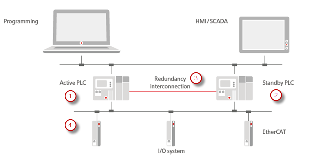
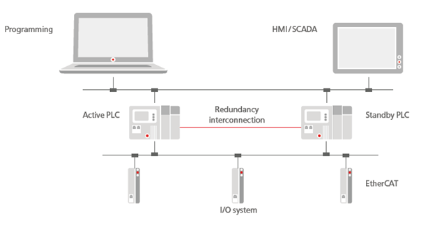
The figure shows an automation scenario consisting of the development environment, the redundant control system of two PLCs, and a machine environment connected via fieldbuses. The application runs in parallel on two PLCs: one PLC is actively working (1), while the other PLC is in standby mode (2). The PLC in standby mode also reads the inputs of the connected fieldbus system (EtherCAT in the example) and continuously synchronizes with the active PLC via the redundancy link (3). This allows the standby PLC to become active immediately in the case of a malfunction and to take control of the fieldbuses (4) without any interruption.
The redundancy link (3) uses TCP or UDP by default. However, communication can also be provided via a manufacturer-specific communication component upon request.
In addition, visualizations can be connected with a redundant control system when they are run as CODESYS WebVisu in a browser. The visualization clients will continue to run almost without any interruption in the event of a switchover.
Note

The video is intended to give you a general overview of this feature. The range of functions of CODESYS Redundancy Configuration as seen there may deviate from the current range of functions.

Basic principles of functionality
The application developer first downloads the application to the first PLC and creates the boot application there. At bootup, the second PLC synchronizes with this controller and also takes the boot application.
After the boot application has been downloaded and initialized, the PLC is ready to execute the first task cycle. Subsequently, all registered memory areas (all IEC data) are transferred to the second PLC. From this point on, redundancy is active and both PLCs execute the application task synchronously. Task execution is synchronized via messages which are exchanged via the redundant link before and after each IEC task.
There is no fixed or preferred active PLC. The operating mode is determined by the boot sequence: the PLC that starts first sends a message to the other PLC via the redundancy link. If no response is received, then the booted PLC still loads the boot application and operates in standalone mode.
If the standby PLC does not receive a message from the active PLC within the configured time, then it will assume that the active PLC has malfunctioned and it will switch to standalone mode. It will take control of the fieldbus I/Os. Conversely, the active PLC also switches to standalone mode if no messages are received from the standby PLC.
If the first PLC is replaced and restarted, then it synchronizes with the other PLC currently in standalone mode as described above and therefore goes into standby mode.
A standby PLC can be switched to simulation mode. The redundancy functionality is disabled during that time. The connection to the fieldbus also remains disabled (as in standby mode). The active PLC switches to standalone mode during this time. Simulation mode can be ended by resynchronizing or restarting. The controller operating in simulation mode then returns to standby mode, provided no errors occur during synchronization or restart.
If errors occur during the update of the boot application, during the transfer of the registered memory areas, or during the redundancy cycle, then the PLC switches to error mode. After that, a resynchronization or a restart is required.
User Interface
Add-on: CODESYS Redundancy Configuration
Tab: Redundancy State
At runtime, CODESYS monitors the redundancy system and displays the current states there. There you can also access the most important redundancy commands and, for example, command a switchover between the states.
Tab: Redundancy Settings
Here you can configure the communication settings of the redundancy link and define the relevant task and a watchdog.
Tab: General
Tab: Visualization
Here you can configure a redundancy link between the web servers which are each running on a PLC. As a result, you can connect visualizations, which are run as CODESYS WebVisu in a browser, with the redundant control system.
Tab: Registered Areas
Here you can manage the data and areas which should be synchronized at runtime.
Tab: Log
Lists the historical redundancy events from the logger of the PLC
EtherCAT (CODESYS GmbH Stack)
PROFINET
CANopen
You configure your fieldbus in the Redundancy Configuration object, on the Redundancy Settings tab, on the Fieldbus Settings tab.
For more information, see the following: Fieldbus Settings tab
Library: Redundancy
The Redundancy Implementation library, which is included by Redundancy library, provides POUs such as SwitchToActive or SwitchToStandby so that you can programmatically access the redundancy components. For example, you can use SwitchToActive to program the switchover of PLCs in active mode.
Library: VisuRedundancy
The VisuRedundancy library implements the redundancy link for the visualization and provides function blocks, for example to monitor activities.
Runtime System
Redundancy components in the runtime system
The runtime system provides two main components for the redundant operation of a control system:
CmpRedundancyThis component handles all functions for managing redundancy operations, including role distribution (active/standby), data synchronization, and monitoring of communication states.
Component for the redundancy link
This component is device-specific and establishes the physical and logical connection between the two controllers. Most devices use an IP-based connection, which is provided via the
CmpRedundancyConnectionIPcomponent.
Functionality
Links two PLCs to a redundant system
Synchronizes the redundancy data
Switches over the operating states of the PLCs
Records the redundancy events in the logger
Note
Events which occur at runtime are recorded on both devices by the loggers of the runtime systems.
The configuration file *.cfg for the runtime of a CODESYS Control Win is stored in ProgramData.
[CmpRedundancyConnectionIP]
Link1.IpAddressLocal=192.168.56.1 ; IP address of redundancy link of local PLC
Link1.IpAddressPeer=192.168.56.101 ; IP address of redundancy link of peer PLC
Link1.Port=1205

[CmpRedundancy]
BootupWaitTime=5000
TcpWaitTime=2000
StandbyWaitTime=50 ; This timeout depends on the quality of real time task and communication system
LockTimeout=20 ; Maximum time of timer lock
Bootproject=Application ; Name of your CODESYS application
RedundancyTaskName=MainTask ; Task name in your CODESYS application
PlcIdent=1 ; PlcIdent=2 on other PLC
Boot application
The boot application is stored identically on both PLCs.
To perform an update, simply load the new boot application to the active controller. The standby controller receives the updated version automatically during synchronization.