Creating a Topology View
Adding a PLC to a topology view
In the topology view, you can display the PLCs entered on the Automation Server and their network topology in a freely selectable screen.
You are signed in to the CODESYS Automation Server.
One or more PLCs are registered on your Automation Server and displayed in the List View.
Click .
Click New Topology View.
In the Create Topology View dialog, specify a name and a description for your topology view.
Click the Select Image button and select an image for the topology view from your file directory. Possible image formats are
jpeg,gif,png, andsvg.Click the Generate button.
The selected image is displayed as topology view.
Click the Edit button.
The Edit Topology View window opens.
Drag the
 element in the image to a PLC.
The
 icon is added for the PLC.
The Properties view opens on the right side of the image for display and editing the properties of the selected PLC in the view.
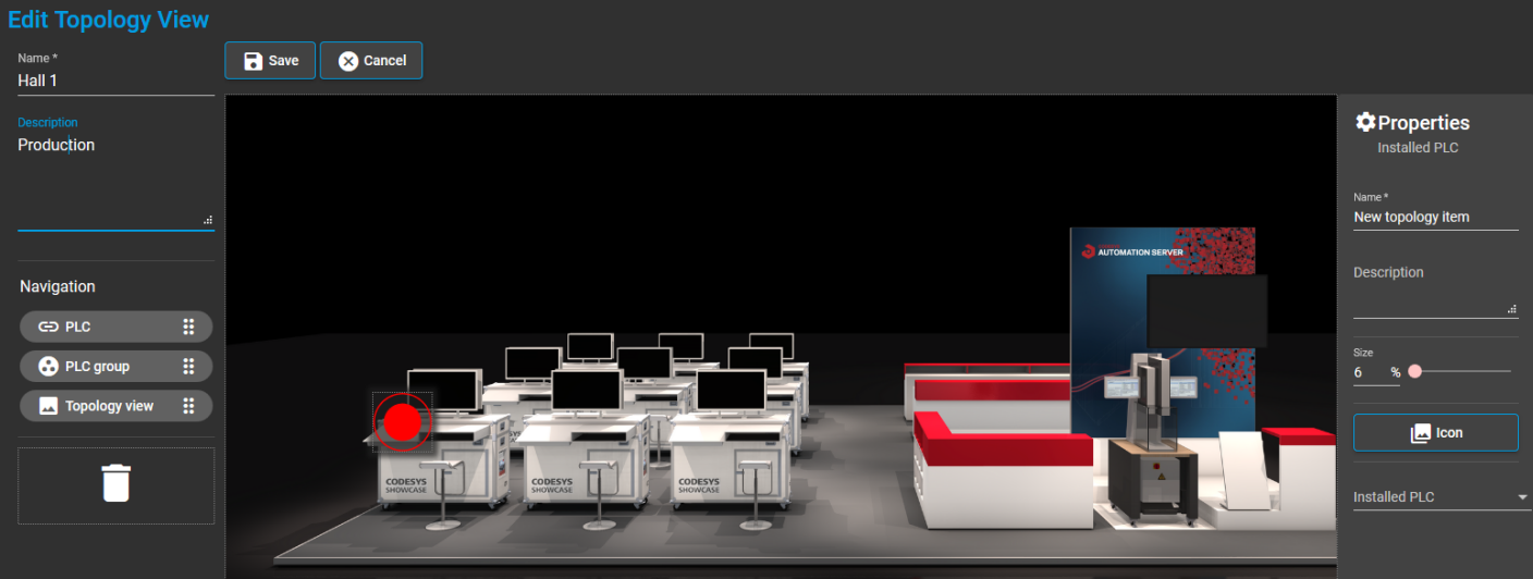
In the following steps, you configure the settings in the Properties view.
Specify the values in the Name and Description fields for the added PLC.
Click Icon. In the Topology Icon dialog, select a default icon or add a custom icon from your file directory.
Click OK to confirm your selection.
You can resize the icon by specifying a value in the Size field, by moving the slider
 , or by means of the arrow keys.
Click Installed PLC.
The Select PLC dialog opens.
Select the desired PLC.
The dialog closes.
The selected PLC is displayed in the Properties in the Installed PLC field.
Click the Save button.
Your recently created topology view is saved and shown.
In this topology view, click the PLC icon
or the icon you selected for the PLC.A dialog opens and displays the serial number of this PLC.
In the dialog, click the Details button.
The PLC Details view opens. The view contains detailed information about the PLC and provides extensive functionalities for handling the PLC. For more information, see: PLC Details
Adding a PLC group to a topology view
Create a new topology view as described in Steps 1–4 of the previous tutorial.
You can also open an existing topology view. To do this, select the entry in the menu and click the desired topology view in the Topology Views window.
Click the Edit button.
The Topology View window opens.
Drag the
 element in the image to the desired location.
The
 icon is added to the image.
The Properties view opens on the right side of the image for display and editing the properties of the selected PLC in the view.
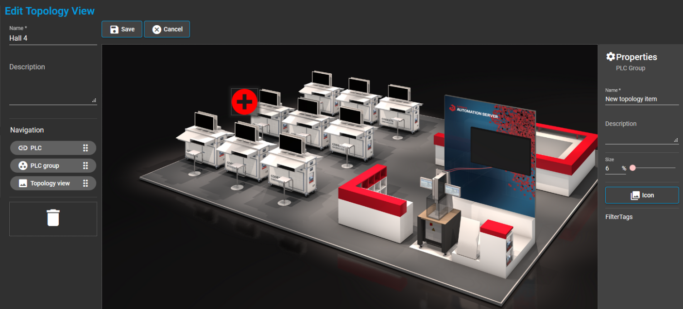
In the following steps, you configure the settings in the Properties view.
Specify the values in the Name and Description fields for the added PLC group.
Click Icon. In the Select Topology Icon dialog, select a default icon or add a custom icon from your file directory.
Click OK to confirm your selection.
You can resize the icon by specifying a value in the Size field, by moving the slider
, or by means of the arrow keys.In the properties, click Tags.
All tags are displayed which you have assigned to PLCs in the List View.
Select the desired tag. Multiple selection is also possible.
Click the Save button.
Your recently created topology view is saved and shown.
In this topology view, click the
icon of your PLC group, or the icon that you added in Step 6.The List View window opens and shows those PLCs that you have added to this PLC group in Step 9 of these instructions .
Reference an existing topology view in a new topology view
Create a new topology view as described in Steps 1–4 of the previous tutorial.
You can also open an existing topology view. To do this, select the entry in the menu and click the desired topology view in the Topology Views window.
Click the Edit button.
The Edit Topology View window opens.
Drag the
 element in the image to the desired location.
The
 icon is added.
The Properties view opens on the right side of the image for display and editing the properties of this added topology view.
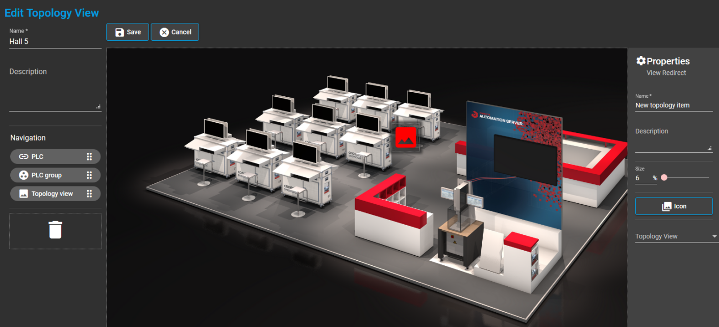
In the following steps, you configure the settings in the Properties view.
Specify the values in the Name and Description fields for the referenced topology view.
Click Icon. In the Select Topology Icon dialog, select a default icon or add a custom icon from your file directory.
Click OK to confirm your selection.
You can resize the icon by specifying a value in the Size field, by moving the slider
, or by means of the arrow keys.In the properties, click Topology View.
The Select Topology View dialog opens.
In the list, select the desired topology view to be referenced in this topology view.
You can also search for the desired topology view by using the search field and then selecting the found topology view.
Click the Save button.
Your recently created topology view is saved and shown.
In the topology view, click the
topology icon, or the icon that you added in Step 6.A dialog with the name of the referenced topology view opens.
Click Go to View.
The referenced topology view opens.
For more information, see: Topology Views