Command: Map I/Os
Symbol: 
This command (category "Composer") opens a dialog to define the mapping between modules and I/O configuration.
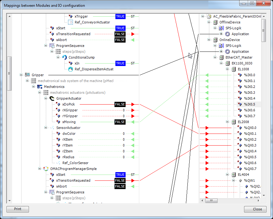
On the left side of the dialog all inputs and outputs of the modules are displayed in a tree structure according the module tree. On the right side there is the structure of the device tree.
The connections of the toplevel modules to the applications is drawn according to the settings of the toplevel modules. This connection cannot be changed in this dialog.
Inputs are displayed with a green connection and a green arrow - outputs are displayed in red.
Open inputs or outputs (with no connection) are displayed with a dotted line.
In case that a ST expression is mapped to the input resp. output, the connection will be displayed with a "ST".
Connections between modules and devices are only possible from input to input or output to output. Furthermore, both connection have to have a compatible data type. Connections between modules are only possible from input to outputs and vice versa. Connections between devices are not possible.
To create a connection the open input or output must be selected. A selected pin is displayed with a blue background. The inputs and outputs are connected by drag and drop. A valid or invalid connection target is indicated with different mouse pointers. Existing connections will be deleted if the input or output is occupied.
If a device or module is collapsed, the connection will be drawn in black because possibly the data direction cannot be determined.
If it is collapsed further (for example, the superordinate device), then the connections will also be hidden. This is done to improve the overview because the line thickness can be reduced in the middle area.
If a connection on the left or right side is selected, the according device will be expanded if it is collapsed.
Arrows show the data direction. A collapsed device shows both green and red arrows if the device uses inputs and outputs. Are there only inputs or outputs, the data direction is also displayed.
In online mode the values of the parameters are displayed on the left side. The values cannot be changed in this view.
With a double click on a module or device the respective object opens in the editor.
Tip
Connections can also be set across application boundaries!
Tip
If a module instance is mapped to the POU pool the connection lines are grayed out. In this situation no IO mappings can be created, but existing mappings can be deleted.
Print: This command allows to print the I/O mappings, which are set, in an overview style.