I/O
This dialog provides information about the inputs and outputs of the module. Inputs and outputs describe the I/O demand of the modules and can be connected to the following:
Inputs and outputs of devices
Inputs and outputs of other module instances
ST expressions or constants (example: for simulation purposes boolean module inputs can be connected to
TRUE)
In online mode, the Online Value column is visible and the current value of the controller is displayed.
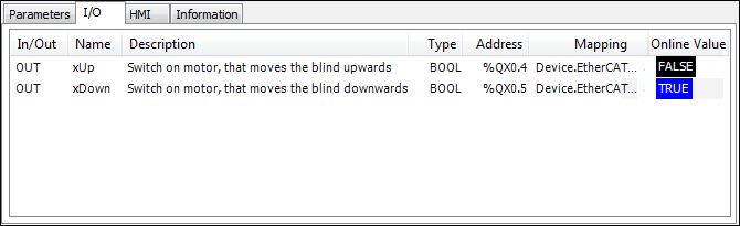
Clicking the Mapping field opens the I/O mapping dialog:
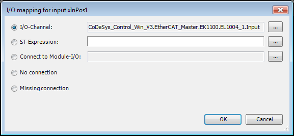
I/O-Channel: Clicking the … button opens another dialog to map the input/output to a device I/O.
ST-Expression: This option allows for mapping the input/output to an ST expression. Clicking the  button opens the Input Assistant to select a variable.
Connect to Module-I/O: This option can be used to map the input/output to an I/O which does not have any connection. Clicking the button opens the Input Assistant to select a module.
No connection: No mapping of the input/output. This option is similar to Missing connection, but it does not generate the warning message.
Missing connection: This option is the default and generates a warning in the message view when generating the project.
Tip
I/Os which are connected automatically by the device generator are indicated by (AUTO) in the IN/OUT column and are disabled. If the mapping is still changed manually, then a warning is displayed that this action will overwrite the automatic mapping.
If an automatically generated connection is overwritten by a manual set connection, then this I/O channel is not considered any longer in the device generator operations.