Adapting the Elements
In the element bar, click the symbol. Then drag the cursor to the editor in order to display the possible insert positions. Drag the cursor to the desired insert position. When the insert position is valid, the cursor will show a plus sign. Release the mouse button there. Alternatively, you could also first click the symbol and then click the desired insert symbol in the editor.
In the element bar, click the desired element and drag it to the desired insert position.
The possible insert positions will be displayed. When the insert position is valid, the cursor will show a plus sign.
Release the mouse button there.
Alternatively, you could also first click the symbol and then click the desired insert symbol in the editor.
The element will be inserted into the ladder diagram.
In the ladder diagram, click an element.
The element will be selected. This is indicated by a light-red background.
Right-click the element to open the context menu.
In the context menu, select the Copy command.
Select a valid insert position and click the Paste command.
In the ladder diagram, click a coil.
The element will be selected. This is indicated by a light-red background.
Right-click the element to open the context menu.
Modify the coil.
In the context menu, select the Storage → Set command.
The coil will become a set coil. The coil variable will retain its value even if the input returns to
FALSE.
Or select the Storage → Reset command in the context menu.
The coil will become a reset coil. When its input becomes
TRUE, it will switch the coil variable toFALSE. The value will remainFALSEuntil the set coil, which has the same variable assigned, resets it.
For more information, see the following: Storage → Set command, Storage → Reset command, Modification → Remove command
In the ladder diagram, click a contact.
The element will be selected. This is indicated by a light-red background.
Right-click the element to open the context menu.
Modify the contact.
In the context menu, select the Edge Detection → Rising command.
The contact will be extended to include edge detection. The edge detection will evaluate the signal change. There will be a reaction to the rising edge (0→1).

Or select the Edge Detection → Falling command in the context menu.
The contact will be extended to include edge detection. The edge detection will evaluate the signal change. There will be a reaction to the falling edge (1→0).

For more information, see the following: Edge Detection → Rising command, Modification → Remove command
Note
Newly inserted blocks initially have enabling.
In the ladder diagram, click a block that does not have EN/ENO.
The element will be selected and displayed in bright red.
Right-click the element to open the context menu.
Extend the block to include enabling:
In the EN/ENO menu, select the EN command.
In the EN/ENO menu, select the ENO command.
The block will be extended to include the
ENenable input and theENOenable output.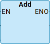
For more information, see the following: EN/ENO → EN / Remove EN command, EN/ENO → ENO / Remove ENO command
In the ladder diagram, click the desired element.
The element will be selected. This is indicated by a light-red background.
Right-click the element to open the context menu.
In the context menu, select the Delete command.