Connecting the Elements to the Circuit
AND connection
The output signal returns TRUE when all input signals are TRUE. This kind of series circuit corresponds to a binary AND-connection.
Drag a network to the editor.
In the element bar, click the
 symbol and drag the element to the insert position (rectangle) in the editor. Release the left mouse button.
A new network will be inserted.
Choose the title AND Gate for the network.
Choose the comment
Binary AND gatefor the network.
Tip
The display of title and comment is controlled in the preferences. If these elements are not visible, then check if the corresponding option is disabled and enable it if necessary.
For more information, see the following: Preferences command
In the element bar, select a contact and drag it to the insert position in the network. Choose the name
bInput_1for the contact.In the element bar, select another contact. In the ladder diagram, click the insert position to the right of the
bInput_1contact. Choose the namebInput_2for the contact.In the element bar, select a coil and drag it to the insert position to the right of the
bInput_2contact. Choose the namebOutput_1for the coil.Declare all input and output variables.
The series circuit will be programmed.
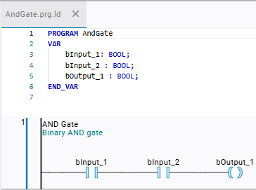
The equivalent ST code:
PROGRAM AndGate
VAR
    bInput_1: BOOL;
    bInput_2 : BOOL;
    bOutput_1 : BOOL;
END_VAR
bOutput_1 := bInput_1 AND bInput_2;
OR connection
The output signal returns TRUE when one of the input signals is TRUE. This kind of parallel circuit corresponds to a binary OR-connection.
Drag a new network to the editor.
In the element bar, click the
symbol and click the element to the insert position (rectangle) in the editor.A new network will be inserted.
Double-click the title and choose the title
OR Gatein the input field that will open.Double-click the comment and choose the comment
Binary OR gatein the input field that will open.
Specify a new contact.
In the element bar, select a contact and drag it to the insert position in the network
OR Gate.Assign the variable
bInput_1to the contact.
Specify a new contact that is positioned parallel to
bInput_1.In the element bar, select another contact.
The network will show the possible insert positions.
Click the insert position (downward-pointing triangle) to the left of the
bInput_1contact.A parallel contact will be inserted into the network.
Double-click the identifier field of the contact.
The input field will open.
Type in
bInput_2.The variable
bInput_2will be assigned to the contact.Select the gray rectangle to the right of the
bInput_2contact.It is light red.
Drag the cursor upwards to the parallel connection until the cursor is displayed as a four-headed arrow.
When the cursor is displayed as a four-headed arrow, the cursor points to a valid position.
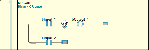
Release the left mouse button.
The connection will be closed.
The contact will be arranged in parallel.
In the element bar, select a coil and drag it to the insert position to the right of the
bInput_1contact. Choose the namebOutput_1for the coil.Declare all input and output variables.
The parallel circuit will be programmed.
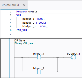
The equivalent ST code:
PROGRAM OrGate
VAR
    bInput_1: BOOL;
    bInput_2 : BOOL;
    bOutput_1 : BOOL;
END_VAR
bOutput_1 := bInput_1 OR bInput_2;
Opening a parallel connection
You can reopen a closed parallel connection by removing the insert position (rectangle) in the part to be removed. Alternatively, you could also drag the rectangles onto each other in order to undo the connection.
The parallel connection is reopened both times.
Trace the connecting line that you want to remove.
The insert position will be displayed.
Click the rectangle.
The rectangle will be highlighted in light red.
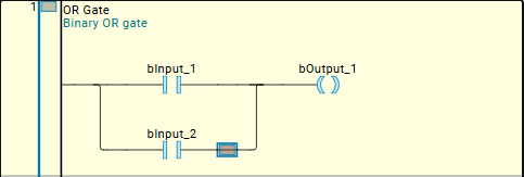
Press the Del key.
The connection will be reopened.
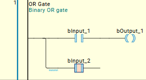
Drag the connecting line to the right of the
bInput_1contact until the insert position is displayed.Click the rectangle while holding down the mouse button.
The rectangle will be highlighted in light red.
Drag the rectangle to the insert position to the right of the
bInput_2contact. Trace the connection until the cursor is displayed as a four-headed arrow.When the cursor is displayed as a four-headed arrow, point to a valid position.
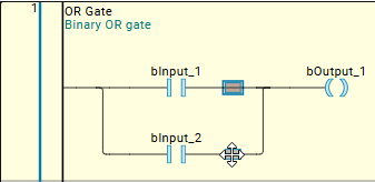
Release the left mouse button.
The part will be removed and the connection will be opened.