Depictorを使用して軸グループを視覚化する
このプロジェクトでは、 CODESYS Depictor 有効なライセンスを持つアドオン。
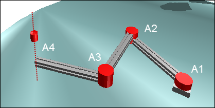
SoftMotionアプリケーションは、軸グループとして構成された4つのロータリードライブで構成されています。最初の3つの軸はTCPをX / Y平面で移動し、4番目の軸はZ平面で移動します。
この例は、Kin_Scara3_Zキネマティック構成でDepictorを使用する方法を示しています。他のキネマティック構成に対して同じ手順をカスタマイズすることもできます。
標準プロジェクトの作成
を使用して標準プロジェクトを作成します CODESYS SoftMotion Win コントローラとSTプログラミング言語。
にライブラリマネージャーを追加します POU 見る。
ライブラリマネージャーを開き、ライブラリを追加します
SM3_DepictorとDepictorBase。
軸の追加とパラメータ化
オブジェクトの下に4つの仮想軸を挿入します SoftMotion一般軸プール 軸にDrive1 ... Drive4という名前を付けます。
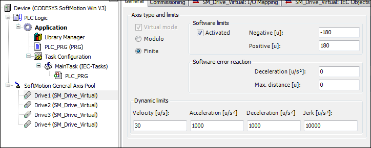
軸ドライブ1、ドライブ2、ドライブ3、およびドライブ4を軸タイプとしてパラメータ化します 有限の ソフトウェアエンドスイッチを使用して-180度から180度に切り替えます。
構成エディター:
詳細については、以下を参照してください。 仮想ドライブ
軸グループの構成
アプリケーションの下に「KinScara」軸グループを追加します。これを行うには、をクリックします 。
構成要素で、をクリックします キネマティクスを選択。を選択 TRAFO.Kin_Scara3_Z キネマティクス。
パラメータを次のように定義します。
dArmLength1、 dArmLength2、 dArmLength3:500
dOffsetA1、 dOffsetA2、 dOffsetA3、 dOffsetZ:0
次のように軸を注文します。
A1:Drive1
A2:Drive2
A3:Drive3
Z:Drive4
注:軸を入力フィールドに直接ドラッグできます。
詳細については、以下を参照してください。 運動学
コントローラプログラムの作成
の中に
PLC_PRGプログラム、インスタンスを宣言しますMC_Powerすべてのドライブの機能ブロック。を作成しますistateステートチャートの変数。VAR Power_Drive1, Power_Drive2, Power_Drive3, Power_Drive4 : MC_Power; istate: INT; END_VAR
実装でステートチャートを定義します。
CASE istate OF
 0:
 1:
 2:
END_CASE
状態のすべてのドライブをアクティブ化する
0。0: Power_Drive1(Axis:=Drive1, Enable:=TRUE, bRegulatorOn:=TRUE, bDriveStart:=TRUE); Power_Drive2(Axis:=Drive2, Enable:=TRUE, bRegulatorOn:=TRUE, bDriveStart:=TRUE); Power_Drive3(Axis:=Drive3, Enable:=TRUE, bRegulatorOn:=TRUE, bDriveStart:=TRUE); Power_Drive4(Axis:=Drive4, Enable:=TRUE, bRegulatorOn:=TRUE, bDriveStart:=TRUE); IF Power_Drive1.Status AND Power_Drive2.Status AND Power_Drive3.Status AND Power_Drive4.Status THEN istate:=istate+1; END_IF
軸がアクティブになったら、軸グループを有効にします(「非アクティブ」から「スタンバイ」に切り替えます)。
VAR
 GroupEnable:MC_GroupEnable;
END_VAR

1:
 GroupEnable(AxisGroup:=KinScara, Execute:=TRUE);
 IF GroupEnable.Done THEN
  istate:=istate+1;
 END_IF
変数を宣言して初期化し、設定値を機械座標に保存します。タイプの2つのインスタンスを宣言します
SMC_POS_REFTCPをデカルト座標と軸座標で表します。VAR Frame: MC_COORD_REF:=(X:=-120, Y:=-25); // This variable stores the cartesian position & orientation of the TCP Pos_Cart: SMC_POS_REF; // This variable represents the position of the TCP in cartesian coordinates coordinates Pos_Axis: SMC_POS_REF := (a := axispos);// This variable represents the position of the TCP in Axis coordinates END_VAR VAR CONSTANT axispos: TRAFO.AXISPOS_REF := (a0 := 0, a1 := 100, a2:=60); END_VAR 2: Pos_Cart.c:= Frame; // To represent the TCP in cartesian coordinates;
のインスタンスを宣言します
MC_MoveDirectAbsoluteスカラロボットを指定の座標に移動します。VAR MoveAbs:MC_MoveDirectAbsolute; // Moves the TCP to the defined coordinates END_VAR 2: MoveAbs(AxisGroup:=KinScara, Execute:=TRUE, Position:=Pos_Axis,CoordSystem:=SMC_COORD_SYSTEM.ACS, BufferMode:=MC_BUFFER_MODE.Aborting,); //move to the defined Axis coordinates //MoveAbs(AxisGroup:=KinScara, Execute:=TRUE, Position:=Pos_Cart,CoordSystem:=SMC_COORD_SYSTEM.MCS, BufferMode:=MC_BUFFER_MODE.Aborting,); //move to the defined cartesian coordinates IF MoveAbs.Done THEN MoveAbs(AxisGroup:=KinScara, Execute:=FALSE); // Waits for the next new coordinates istate:=2; END_IFタイプの変数を宣言します
SMC_GroupReadSetPositionデカルト座標と軸座標でロボットの現在の値を読み取ります。VAR Car_pos, Axis_pos :SMC_GroupReadSetPosition; //to read the current axis values END_VAR 2: Car_pos(AxisGroup:=KinScara, CoordSystem:=SM3_Robotics.SMC_COORD_SYSTEM.MCS, Enable:=TRUE); // to read the current position in cartesian coordinates Axis_pos(AxisGroup:=KinScara, CoordSystem:=SM3_Robotics.SMC_COORD_SYSTEM.ACS, Enable:=TRUE); // to read the current axis values
PLC_PRGプログラム全体
プログラムを比較し、不足しているプログラム部分を追加します。
宣言
PROGRAM PLC_PRG
VAR
    Power_Drive1, Power_Drive2, Power_Drive3, Power_Drive4 :MC_Power;
    istate: INT;

    GroupEnable:MC_GroupEnable;

    Frame:MC_COORD_REF:=(X:=-120, Y:=-25); // This variable stores the cartesian position & orientation of the TCP
    Pos_Cart:SMC_POS_REF; // This variable represents the position of the TCP in cartesian coordinates coordinates
    Pos_Axis:SMC_POS_REF := (a := axispos);// This variable represents the position of the TCP in Axis coordinates

    MoveAbs:MC_MoveDirectAbsolute; // Moves the TCP to the defined coordinates (PTP)

    Car_pos,Axis_pos :SMC_GroupReadSetPosition; //to read the current position of the TCP in Cartesian and Axis Coordinates and display it on the visu

    scara_Config:trafo.Kin_Scara3_Z_Config; // To set the configuration of the SCARA_3_Z
    kin_Config:SMC_SetKinConfiguration; // To set the defined configuration of SCARA_3_Z to the axis group used
    nPeriod:DINT:=0; // SCARA_3_Z Period
    Xelbow:BOOL:=TRUE;

END_VAR
VAR CONSTANT
    axispos : TRAFO.AXISPOS_REF := (a0 := 0, a1 := 100, a2:=60);
END_VAR
実装
CASE istate OF

0:
 Power_Drive1(Axis:=Drive1, Enable:=TRUE, bRegulatorOn:=TRUE, bDriveStart:=TRUE);
 Power_Drive2(Axis:=Drive2, Enable:=TRUE, bRegulatorOn:=TRUE, bDriveStart:=TRUE);
 Power_Drive3(Axis:=Drive3, Enable:=TRUE, bRegulatorOn:=TRUE, bDriveStart:=TRUE);
 Power_Drive4(Axis:=Drive4, Enable:=TRUE, bRegulatorOn:=TRUE, bDriveStart:=TRUE);

 IF Power_Drive1.Status AND Power_Drive2.Status AND Power_Drive3.Status AND Power_Drive4.Status THEN
  istate:=istate+1;
 END_IF

1:
 GroupEnable(AxisGroup:=KinScara, Execute:=TRUE);

 IF GroupEnable.Done THEN
  istate:=istate+1;
 END_IF

2:
 scara_Config(xElbowRight:=Xelbow, nPeriodA3:=nPeriod);
 kin_Config(AxisGroup:=KinScara,ConfigData:=scara_Config.Config, Execute:=TRUE);
 Pos_Cart.c:=Frame; // To represent the TCP in cartesian coordinates

 Car_pos(AxisGroup:=KinScara, CoordSystem:=SM3_Robotics.SMC_COORD_SYSTEM.MCS, Enable:=TRUE); // read the current position in cartesian coordinates
 Axis_pos(AxisGroup:=KinScara, CoordSystem:=SM3_Robotics.SMC_COORD_SYSTEM.ACS, Enable:=TRUE); // read the current position in Axis coordinates

 MoveAbs(AxisGroup:=KinScara, Execute:=TRUE, Position:=Pos_Axis,CoordSystem:=SMC_COORD_SYSTEM.ACS, BufferMode:=MC_BUFFER_MODE.Aborting,); //move to the defined axis coordinates
 //MoveAbs(AxisGroup:=KinScara, Execute:=TRUE, Position:=Pos_Cart,CoordSystem:=SMC_COORD_SYSTEM.MCS, BufferMode:=MC_BUFFER_MODE.Aborting,); //move to the defined cartesian coordinates

 IF MoveAbs.Done THEN
  MoveAbs(AxisGroup:=KinScara, Execute:=FALSE); // Waits for the next new coordinates
  istate:=2;
 END_IF
END_CASE
Depictorプログラムの作成
アプリケーションの下に「プログラム」タイプの新しい「Depic」POUを追加します。これを行うには、をクリックします 。
タイプの変数を宣言します
SM3_Depictor.SMC_R_Scara3_Z_Data。変数を宣言するLrSizeタイプのLREAL変数を値100で初期化します。VAR ScaraTrafo : SM3_Depictor.SMC_R_Scara3_Z_Data; LrSize:LREAL:=100; END_VAR
実装に関数ブロックへの呼び出しを挿入します。
ScaraTrafo(AxisGroup:=KinScara, trf:=KinScara.trafo);
「Depic」POUをに追加します 主な任務。
Depictorの構成
アプリケーションの下に「Depictor」オブジェクトを追加します。これを行うには、をクリックします 。
オブジェクトをダブルクリックします。
を選択 ポーズ Depictorツリーの要素。
クリック 。
NS 箱 ポーズの下に要素が追加されます。
を選択 DepictorRef。 要素のプロパティのオプション。
クリック
 ボタン。
ボタン。を選択 SMC_R_Depictor_Scara3_Z からのオブジェクト
SM3_Depictor図書館。インターフェイス変数を次のように定義します。
fb:Depic.ScaraTrafo
lrZ_:Drive1.fSetPosition
lrZmin:10
lrZmax:-50
lrSize:Depic.LrSize
xShowPlane:0
ビジュアライゼーションの作成
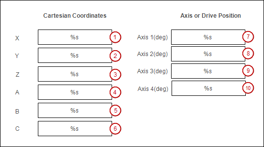
デカルト座標と軸座標を表示および変更できる視覚化画面を作成します。
アプリケーションの下に「視覚化」オブジェクトを追加します。これを行うには、をクリックします 。
エディターでビジュアライゼーションを開きます。
を挿入します 矩形 視覚化要素(1)。
要素のプロパティを変更します。
: %NS
:
PLC_PRG.Car_pos.Position.c.X入力方式: VisuDialogs.Numpad
別の変数を使用する:
PLC_PRG.Frame.X
他を挿入します 箱 視覚化要素。
要素(2)と(3)のプロパティを変更します。
: %NS
:
PLC_PRG.Car_pos.Position.c.YまたPLC_PRG.Car_pos.Position.c.Z入力方式: VisuDialogs.Numpad
別の変数を使用する:
PLC_PRG.Frame.YとPLC_PRG.Frame.Z
要素(4)、(5)、および(6)のプロパティを変更します。
: %NS
:
PLC_PRG.Frame.AまたPLC_PRG.Frame.BまたPLC_PRG.Frame.C
要素(7)、(8)、(9)、および(10)のプロパティを変更します。
: %NS
:
PLC_PRG.Axis_pos.Position.a.a0またPLC_PRG.Axis_pos.Position.a.a1またPLC_PRG.Axis_pos.Position.a.a2またPLC_PRG.Axis_pos.Position.a.a3入力方式: VisuDialogs.Numpad
別の変数を使用する:
PLC_PRG.Pos_Axis.a.a0とPLC_PRG.Pos_Axis.a.a1とPLC_PRG.Pos_Axis.a.a2とPLC_PRG.Pos_Axis.a.a3
視覚化要素にラベルを付けます ラベル エレメント。
プログラムの開始とテスト
プロジェクトの視覚化で軸の値を変更できます。アクティブな移動コマンドをコメントアウトした場合(MoveAbs...、...)プログラム内 PLC_PRG 2番目の移動コマンドのコメントを削除すると、デカルト座標を変更できます。
プロジェクトをビルドし、PLCにダウンロードします。
プロジェクトでDepictorオブジェクトのエディターを開きます。
ビジュアライゼーションに切り替えて、軸の値またはデカルト値を変更します。 Depictorでスカラロボットの動きを観察します。