Working in the Statechart Editor
In the statechart editor, you graphically implement a statechart.
Implementing a statechart
You can insert states which call methods or actions. When you insert transitions, you can define conditions for a state transition. When inserted, the condition is TRUE by default, as represented as  . After that, you can change this value to call an action or method.
You can implement control structures by inserting pseudo states. To improve the overview, you can group states in composite states for which you implement a common behavior with completion transitions. You can use exception transitions to program the behavior in the event of an error.
CODESYS is started.
Click .
Specify the name and location, and select the Standard Project template.
The Standard Project dialog opens.
For PLC_PRG, select the UML Statechart (SC) implementation language.
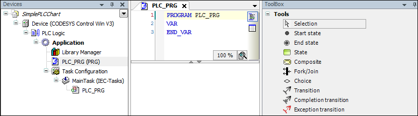
In the device tree, click the program
PLC_PRG.The editor consists of a window for the declaration and a window for the graphical implementation. In the ToolBox view, elements are listed which you can use to create a statechart.
Drag a Start state to the implementation.

Click the start state.
The
 symbol for a completion transition is displayed.
Click the
transition.A mouse pointer is displayed with a line as the transition and a pointer as the element.
Click below the start state.
A state is inserted.
Double-click the default name.
A line editor opens.
Specify the name
PowerOff.
Click the state, and then click the transition. Then click below the state.
A transition is inserted with an additional state.
Specify the name
Idle.Insert a transition to still another state named
DoIt.Hover over the state
DoIt.Icons are displayed in the state to added actions or methods.

Click the
 symbol.
The state is extended by a DO action.
Hover over the DO symbol.
The
 symbol is displayed on the right.
Click the icon.
The New action object dialog opens. There you can configure the initial settings for a POU that is subordinate to the program
PLC_PRG. The object can be either a method or an action.Select an action and click Add to exit the dialog.
In the device tree, the new and empty action
PLC_PRG_DoIt_DOis inserted belowPLC_PRG. In the stateDoIt, the DO action is listed by name. The action is opened in the editor.Declare control variables and local variables in the declaration part of
PLC_PRG.PROGRAM PLC_PRG VAR iCounter: INT; bReady: BOOL; bDoIt: BOOL; bPowerOn : BOOL; bPowerOff : BOOL; END_VARIn the action
PLC_PRG_DoIt_DO, implement code for flow and control.iCounter := iCounter + 1; IF iCounter > 100 THEN iCounter := 0; bReady := TRUE; RETURN; END_IFHover over the
DoItstate and click the symbol. Then click New in the section and confirm the dialog.
For the state
Doit, the EXIT actionPLC_PRG_DoIt_EXITwas added.Implement the code there.
bReady := FALSE;
bDoIt := FALSE;
Add a transition from the state
DoItto the stateIdle.For the transition, click the
symbol.The line editor opens. If you have selected the SmartCoding feature, then a list box with all declared variables is displayed.
Select the Boolean variable
bReady.The variable is used as a control variable to switch to the state
Idle.Add a transition from the state
Idleto the statePowerOff.For the transition, click the
symbol.The line editor opens. If you have selected the SmartCoding feature, then a list box with all declared variables is displayed.
Specify the control variable
bPowerOff.In the device tree, select the program
PLC_PRGand added an object Action namedPowerDown.Implement the action.
bPowerOn := FALSE;
In the editor, select
PLC_PRG.In the transition from the
Idlestate to thePowerOffstate, click the symbol to call an action.
A list box with actions is displayed.
Select the action
PowerDown.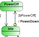
Implement the condition from the state
PowerOffto the stateIdle.bPowerOnIn the device tree, select the program
PLC_PRGand added an object Action namedPowerUp.Implement the code of the action.
bPowerOff := FALSE;
In the editor, select
PLC_PRG.In the transition from the
Idlestate to thePowerOffstate, click the symbol.A list box with actions is displayed.
Select the
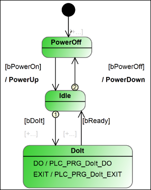
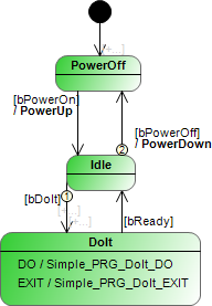
PowerUpaction and set the variable betweenIdleandDoIttobDoIt.The statechart is implemented. All transitions have a condition. The actions which are called are implemented.
Click to compile the application.
The compilation has completed without errors.
Editing element properties
In the statechart editor, select an element.
All properties of the element are listed in the Properties view.
Edit the properties in the Value column.
You can edit the DoIt state in the view.
Select the state
Doitin the statechart editor.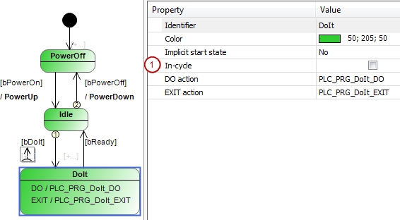
In the Properties view, the option In-cycle (1) is cleared.
Select the option.
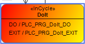
The state is now in-cycle, not clocked by bus cycles.
Multiselection
When Selection is selected (default setting) in the ToolBox view, you can drag a box over multiple elements in the editor. Then all the captured elements are selected. You can also press the Ctrl key and click each element.
Create Image
You can create and use a graphic in PNG format from your statechart object.
In the device tree, select a statechart object.
In its context menu, click Create Image.
The Create Image dialog opens.
Select the desired options.
Click OK to confirm the dialog.
The image file is saved.
Switch to your desktop.
Open the link.
A default editor opens and shows the image.