Designing and Developing
When you program graphically in the class diagram, your changes automatically cause adaptations for the objects in the POUs view and Devices view. New objects are inserted in their basic structure, and existing objects are adapted. For example, you can insert declarations in the POUs via the class diagram.
This allows you to design the architecture of your application in a class diagram and get the suitable POUs synchronously. Then you supplement the implementations in the POUs.
The following steps create a class diagram for an application.
1. Creating a project
Open CODESYS.
Click .
Specify the name and location, and select the Standard Project template.
The Standard Project dialog opens.
For PLC_PRG in, select the Structured Text (ST) implementation language.
The project is created.
Select the Application code and click .
The Add UML Class Diagram dialog opens.
Specify the object name
CD_Simple.Select the Import project structure to active class diagram option.
Click Add.
Save the project as
SimpleMachine.project.
2. Identifying interfaces
Interfaces determine publicly visible methods and properties in order to implement classes.
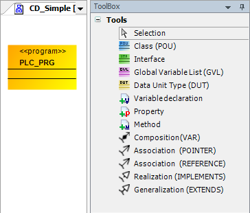
Open the editor of the class diagram
CD_Simple.In the ToolBox view, select an interface.
Drag the interface to the editor.
The Add Interface dialog opens.
Specify the name
IBaseMachine. Click Add to exit the dialog.In the ToolBox view, select a method.
Drag the method to the interface.
The Add Interface method dialog opens.
Specify the name
DoIt.Specify the return type
BOOL. Click Add to exit the dialog.In the ToolBox view, select a property.
Drag the property to the interface.
The Add Interface property dialog opens.
Specify the name
StateNumber.Specify the return type
INT. Click Add to exit the dialog.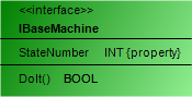
Tip
For more information about interfaces, see: Object: Interface and Object: Interface Property
3. Identifying classes and implementing an interface
Different classes that implement the same interface contain the same methods and properties. If the interface is changed or extended later, then this will affect all implementing classes.
Open the editor of the class diagram
CD_Simple.In the ToolBox view, select a class.
Drag the class to the editor.
The Add POU dialog opens.
Specify the name
FB_Machine.Select the Function block option.
For implementation language, select UML Statechart (SC). Click Add to exit the dialog.
The class
FB_Machineis added to the class diagram.Select the class.
Command icons are displayed above the class.
Click the
 Realization (
IMPLEMENTS) command icon and click theIMachineinterface.The Select Implementation Language dialog opens.
Select Structured Text (ST).
The class
FB_Machineinherits the properties and methods of the interface and therefore implements the interfaceIMachine.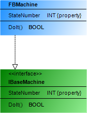
4. Generalizing
In generalization, a class inherits the properties and methods of another class.
Open the editor of the class diagram
CD_Simple.In the ToolBox view, select a class.
Drag a class to the editor.
The Add POU dialog opens.
Specify the name
FB_Machine_A.Select the Extends option and specify the class
FB_Machinein the input field.The function block
FB_Machineis extended and therefore it is a generalization ofFB_Machine_A.For implementation language, select UML Statechart (SC). Click Add to exit the dialog.
The class
FB_Machine_Ais created in the class diagram. A generalization exists between the classesFB_MachineandFB_Machine_A.FB_Machine_Ainherits its properties and methods fromFB_Machine.In the ToolBox view, select the Variable declaration element and drag it to the class
FB_Machine_A.The Auto Declare dialog opens.
Specify the name
iCounterand the data typeINT. Click OK to exit the dialog.Now the class
FB_Machine_Ahas its own variables in addition to the inherited properties and methods.In the class
FBMachine_A, select the methodDoIt()and press the Del key.The method is removed from the diagram, as well as the object in the Devices view. The inheriting function block
FBMachine_Adoes not need its own special implementation for the method. Instead, it calls the methodDoItof the base function blockFBMachinewhen necessary.Note
When you call methods, which are assigned to a base function block and inherited, use the pointer
SUPER.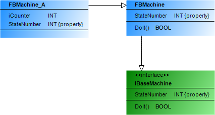
Tip
For more information, see Extending a Function Block and Pointer: SUPER.
5. Instantiate
Open the editor of the class diagram
CD_Simple.Select the program
PLC_PRG.Command icons are displayed above the program.
Click the
 Composition (
VAR) command icon and click theFB_Machine_Aclass.The Variable declaration dialog opens.
Specify the name
fb_A.The object
fb_Aof the classFBMachine_Ais instantiated. Now, the instance of the class in its concrete form is generated at runtime.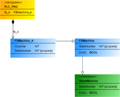
The class diagram displays all objects that are relevant for generating the application code. Above all, however, the class diagram visualizes the relationships between the objects: Who implements whom? Who inherits from whom? Who instantiates what? Otherwise, this information is hidden in the declaration and for example cannot be seen in the Devices view.
6. Implementing
Open the function block
FBMachine.Declare the function block variables.
FUNCTION_BLOCK FBMachine IMPLEMENTS IBaseMachine
VAR
    iState: INT;
    iMachine : INT;
END_VAR
Implement the function block.
iState := iState + 1; // Dummy for control ID
Implement its method
DoIt.METHOD PUBLIC DoIt : BOOL iMachine := iMachine + 1; // Dummy
Implement the Get method of the property
StateNumberofFBMachine.StateNumber := iState;
Implement the Set method of the property
StateNumberofFBMachine.iState := StateNumber;
Open the function block
FBMachine_A.Declare the function block variables.
FUNCTION_BLOCK FBMachine IMPLEMENTS IBaseMachine
VAR
 iCounter: INT;
END_VAR
Implement the function block.
iCounter := iCounter + 1;
Implement the Get method of the property
StateNumberofFBMachine_A.StateNumber := iCounter;
Implement the Set method of the property
StateNumberofFBMachine_A.iCounter := StateNumber;
Click .
The application is compiled without errors.
Download and start the application.
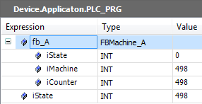
You can monitor the function block instance
fb_A.