Analysis
You can create class diagrams from existing projects and applications for analysis or documentation purposes.
Displaying an application as a class diagram
Open a project that you did not create yourself.
The sample project illustrated below applies the object-oriented concept and for this it uses language elements such as
EXTENDSorIMPLEMENTS.Tip
The complete sample project is included in the installation (
OO.project).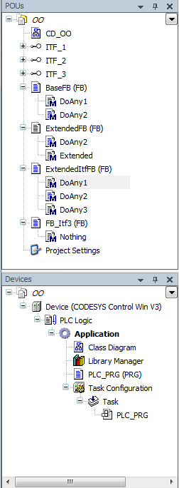
Get an overview of the content of the project and the objects in the POUs view and the Devices view. You can determine the functionality of the objects from the object type, which is indicated by the symbol in front of the object name.
In the following, we create a UML class diagram that represents the project structure shown above.
Select the application in the device tree. Click .
The Add UML Class Diagram dialog opens.
Select the Import project structure to active class diagram option. For import options, clear the Collapse elements option.
The class diagram editor opens. The POUs below the application are represented as a class diagram. In this case, it is only the element for the PLC_PRG POU.
PLC_PRGuses instances of POUs from the POUs view. The structure information for the program exists in the element, but the elements for the instantiated POUs from the POUs view still have to be inserted manually.Select the POUs view.
Select one POU at a time and drag it to the class diagram editor.
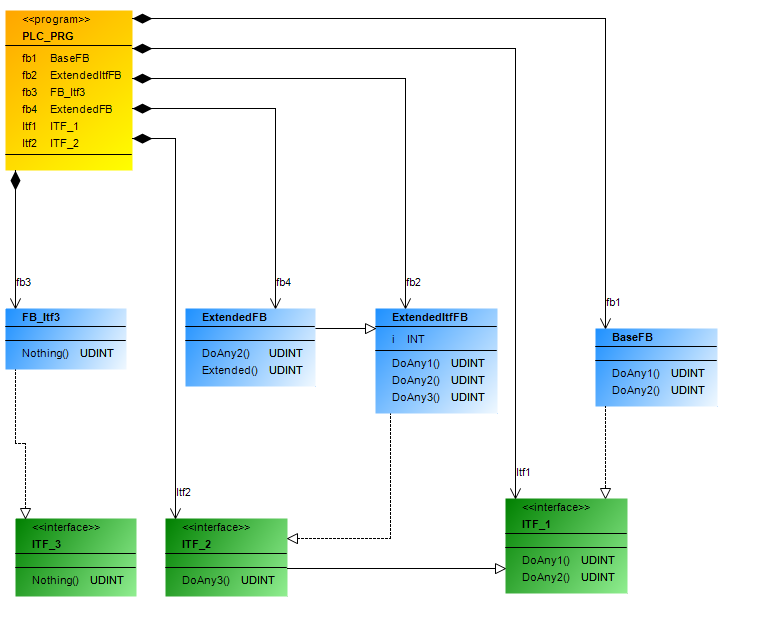
The class diagram illustrates the relationships between the POUs, as well as the static structure of the application.
Select the Import project structure to active class diagram option.
The class diagram illustrates the relationships between the POUs, as well as the static structure of the application.
The class diagram editor opens. The POUs of the application are represented as a class diagram.
The generated class diagram shows the structure of the project
OO.project.
Displaying a class diagram from parts of the project
Using the  command icon and the cross-references listed in the ToolBox view, edit a class diagram so that only the desired part of the static structure is displayed.
Select the Import project structure to active class diagram option.
The class diagram editor opens. The POUs of the application are represented as a class diagram.
The following class diagram shows the structure of the project
OO.projectfor example.In the class diagram, select the interface
ITF_1.Command icons are displayed above the interface.
Click the
command icon.The interface is removed from the class diagram without removing the POU itself from the project. The class diagram represents only part of the project.
Select the class
BaseFB.The outgoing cross-references of the selected element are displayed In the ToolBox view. For example, this is the generalization for the class
FBMachine.Drag the cross-reference to the class diagram.
The element is displayed again with all relationship arrows.