Performance
The planning of movements is done in a separate task because the computation is CPU-intensive. This separate task is referred to as the planning task and it runs in parallel with the bus task. If the performance of the PLC is not sufficient to plan the path in the planning task in time for the bus task, then these are performance problems.
Performance problems in movement planning can lead to the SMC_CP_QUEUE_UNDERRUN error, but they can also lead to a movement which is jerky or slower than expected. For information about the SMC_CP_QUEUE_UNDERRUN error, see the Common Errors chapter. The diagnosis of performance-related problems with movements is described below.
Diagnosis in case of slow or jerky movements
If there are no performance problems, then each movement is planned in such a way that at least one of the effective limits is reached during the entire movement. As an example, consider a simple two-dimensional gantry with two axes X and Y and a PTP movement from position (0,0) to (10,-10). The maximum axis velocity is 20, the maximum axis acceleration is 100, and the maximum axis jerk is 1000.
The expected movement looks like this:
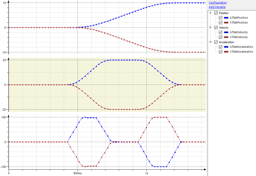
Acceleration is first established with a maximum jerk until the acceleration limit value of 100 is reached. After a short phase of constant acceleration, the acceleration is reduced again with a maximum jerk so that the velocity limit value of 20 is reached with acceleration 0. After a phase of constant velocity, deceleration takes place so that the target position is reached with velocity and acceleration 0.
There are two possible reasons why the real movement deviates from this ideal curve:
The planned movement does not correspond to the ideal curve due to performance problems in the planning task.
The planned movement corresponds to the ideal curve, but the robot does not execute it as expected.
Case 1: Performance problems of the planning task
If there are problems with the performance during the planning, then the movement might look like this instead:
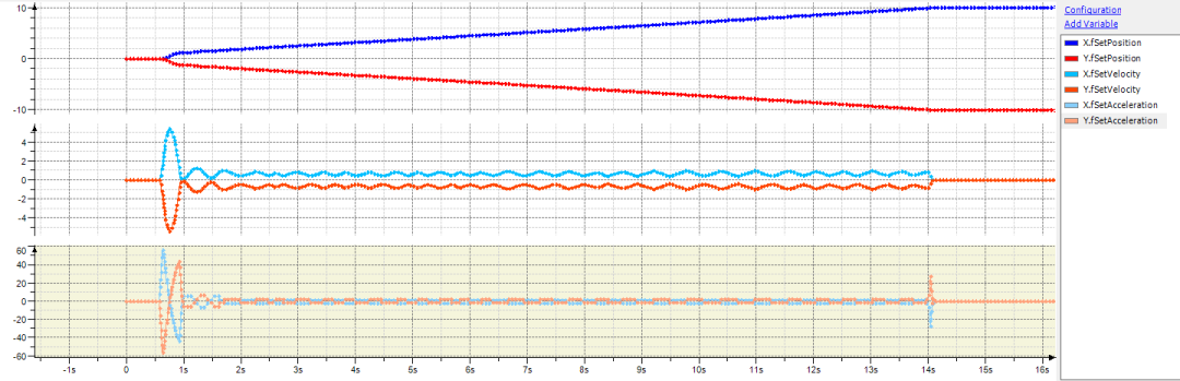
This is because the movement is planned in the planning task in parallel to execution in the bus task. On average, the planning task needs to provide as much trajectory as the bus task requires. If the performance is not sufficient for this, then the movement is slowed down. This leads to the wavy velocity curve.
The first and most important tool for diagnosing such problems is the trace. In addition to the fSetPosition, fSetVelocity, and fSetAcceleration variables for each axis, the numTimeBudgetExceeded and numSlowDownLowIpoQueue outputs of the SMC_GroupReadPlanningStatistics function block should also be recorded. If these counters increase continuously, then there is a performance problem.
Note
Similarly to the fSetPosition, fSetVelocity, and fSetAcceleration variables, there is also the fSetJerk variable for the jerk. It should be noted that the jerk is not the average jerk which is applied during the bus task cycle (as often expected), but rather the instantaneous jerk at the end of the cycle. Therefore, FSetJerk has only limited significance for diagnosing performance problems.
Ways to improve the movement
The following list contains steps to handle performance problems:
Adjustment of the limit values for velocity, acceleration, and jerk:
The longer it takes to decelerate from the current velocity to standstill, the greater the computing power required
A high effective limit value for velocity and low effective limit values for acceleration and jerk are therefore more likely to lead to performance problems.
In particular, the limit values for acceleration and jerk should therefore not be set unnecessarily low
Increase the priority of the planning task or decrease the priority of the other tasks if they are blocking the planning task. The planning task should have the second highest priority after the bus task.
Assign the planning task to a dedicated core if multiple CPU cores are available (seeConfiguration of the Planning Task).
Use
SMC_TuneCPKernelto increase the value of thefPlanningIntervaland/orfSyncBufferDurationplanning parameters.The
fPlanningIntervalparameter specifies the maximum planning increment (in seconds). The cycle time of the planning task should not permanently exceed this value. A higher value reduces the computing power, but can also cause the set limit values for velocity, acceleration, and jerk not to be not fully utilized. From a starting value of 0.016 seconds (the default value since CODESYS SoftMotion version 4.6.0.0), the value should be gradually increased until the performance is acceptable.The
fSyncBufferDurationparameter specifies the size of the buffer between the planning and bus task. The peak cycle times of the planning task must not exceed this value. A higher value can compensate for peaks in the cycle time of the planning task. At the same time, however, this also increases the latency for the execution of interrupts and aborting movements.
Case 2: Robot does not follow the planned movement as expected
If the robot does not follow the planned movement as expected, then this may be due to the following reasons:
Insufficient real-time capability of the controller
Control loop problems of the drives
On a non-real-time-capable controller such as the CODESYS Control Win, or a Linux-based controller without a real-time patch of the underlying Linux system, too slow or jerky movements can occur even with sufficient performance. This happens if the bus task is not executed on time in the configured time frame.
Ways to improve the movement
On the "Monitoring" tab of the task configuration 1, check if the task jitter of the bus task 2 is too high. This may be the case either because the bus task is being displaced by a task with the same or higher priority, or because the controller is not sufficiently real-time capable.
If the jitter is too high and you have already made sure that the bus task has the highest priority, then the real-time capability of the controller is not sufficient. In this case, use a controller with better real-time properties.
If there are control loop problems in the drive, then you should adjust the control loop parameters. The torque feed forward control can also improve the control loop performace.
For more information, see: Torque Limitation and Torque Feed Forward Control
1: It is advisable to reset the measured values of the task monitoring in the context menu because the first PLC cycle after starting the application often has an increased duration and increased jitter.
2: Jitter values up to approx. 20 us are very good, and values up to approx. 100 us are good. Depending on the used drives, operation with higher jitter values may also work. Jitter values which reach the order of magnitude of the task interval of the bus task can result in the error pattern described above.