Torque Limitation and Torque Feed Forward Control
The torque limitation of CODESYS SoftMotion makes sure that specified limits of the torques or forces of the drives from being exceeded during coordinated movements. These limits of torques and forces are respected in addition to the existing limits for the velocity, acceleration, and jerk of the drives. The requirement for this is a dynamic model for the applied kinematics in the form of a function block which implements the ISMDynamics interface from the SM3_Dynamics library. Basically, a AxesStateToTorque method is needed, which calculates the required torques for a given state of the axes (for their position, velocity, and acceleration).
Besides the torque limitation, a dynamic model allows for the calculation of set torques for a torque feed forward control. You can find an application example in the chapter Dynamic Robot Model.
Use cases
In many kinematics, especially serial kinematics, there is a coupling of multiple joints or all joints. A simple example of this is the double pendulum with drives in the joints as shown below:
Use case 1 |
Use case 2 |
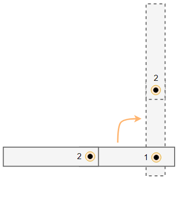
The drive in the first joint performs a 90° rotation; the second joint should not move (use case 1). Assuming a passive second joint, it is easy to imagine that the second limb of the double pendulum will rotate to the left due to its inertia. To prevent this rotation, the drive in the second joint has to generate a torque to the right. Therefore, the movement of the first drive requires a reaction from the second drive.
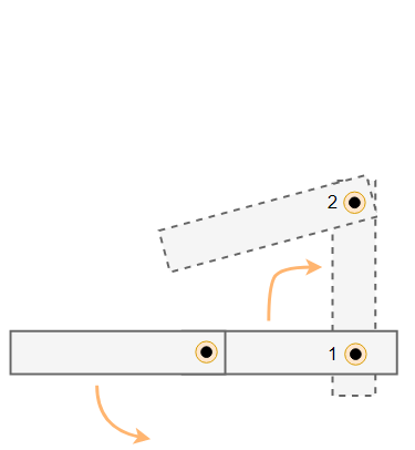
Coupling in the opposite direction exists, for example, in the case where the first drive should move at constant velocity while the second drive retracts the second limb of the double pendulum (use case 2). This reduces the inertia matrices of the double pendulum with respect to the first joint. To obtain the angular momentum (the product of the inertia matrices and the angular velocity), the angular velocity of the first joint needs to be increased. To hold the angular velocity constant, the angular momentum needs to be decreased by changing the torque of the first drive against its direction of rotation. Therefore, the movement of the second drive requires a reaction from the first drive.
Without a dynamic model, only the set position, the set velocity, and the set acceleration can be sent to the drive. In the first case, a constant set position is defined for the second drive, regardless of whether or not the first joint is moving. The control unit in the second drive needs to be able to deal with the fact that a torque has to be generated in one case and not in another case for the same set values. The behavior is similar in the second case. Here, the same constant set velocity is specified to the first drive, regardless of whether or not the second joint is moving. Here too, the control unit in the drive needs to deal with the fact that different torques have to be generated for the same set values.
With a dynamic model, the set torques can be calculated and sent to the drives. There they can be used as a feed forward dimension for the control units. As a result, the control unit receives additional information which allows for an improvement of the control quality.
The torque limitation allows for more precise adherence to the limits of the drive. In many cases, it is not the limitation of the velocity or acceleration of the drive that is decisive, but the limitation of the torques. The advantages of torque limitation become clear from the example of the double pendulum as described above when the following movements are compared: a movement of the first drive with the second limb retracted and a movement of the first drive with the second limb extended. In the retracted state, the inertia matrices with respect to the first joint are less than in the extended state. For the same movement (the same velocity and acceleration curves of the drive), a greater torque is therefore required in the extended state than in the retracted state. Without a dynamic model, the velocity and acceleration limits need to be set so that the torque limits are adhered to in both states. This can cause the first drive to move at a lower velocity or acceleration in the retracted state than would be necessary to adhere to the torque limits of the drive. With a dynamic model, the torque limits can be configured, taken into account when planning the movement, and therefore fully utilized in both states.
A slightly more complex example is the first case as described above, where the first drive is moving and the second drive should hold its position. The required torque in the second drive in order to hold its position depends on the movement of the first drive. If the first drive accelerates too sharply, then in principle the torque limit of the second drive may be violated. Without a dynamic model, this can only be prevented by configuring the acceleration limits of the first drive accordingly. With a dynamic model, the configured torque limit of the second drive can be taken into account when planning the movement and the acceleration of the first drive can be limited.
In the case of more complex movements or kinematics, the coupling effects described here come together with even more coupling effects. A dynamic model allows these couplings to be taken into account, resulting in better set value specifications and better adherence to the limits of the drives.
Configuration of the dynamic model
An existing dynamic model in the form of a function block which implements the ISMDynamics interface can be assigned to an axis group by means of the SMC_GroupSetDynamics function block. Besides the dynamic model, the function block also has to be used to configure the direction and magnitude of the gravitational acceleration in the form of a vector in the machine coordinate system.
Consideration of loads
Additional loads (for example, gripped objects or attached tools) can be taken into account by means of the SMC_GroupSetLoad function block and changed at runtime. The ExecutionMode input of the function block can be used to define when a load change should take effect (for example, immediately or only after the current movement has been completed).
Important
Continuation with MC_GroupContinue: When continuing, every movement which is stored in the continue data keeps the load with which it was originally commanded. Any movement which is commanded after the continuation uses the last set load.
Consideration of a gearbox
The set torques are calculated for the gearbox output and are not automatically converted to the drive. The SMC_SetAdditionalConversionFactors function block can be used to configure an additional conversion factor for the torque for each axis. The gearbox can also be taken into account in this way.
Units
Forces and torques and their limits are basically specified in the application in newtons (N) or newton meters (Nm). Before set forces or set torques are sent to the drives, a rescaling may be done. For this, the CiA 402 standard requires, for example, that set torques are sent to the drive in thousandths of the rated torque (in mNm).
The unit for lengths is user-specific in SoftMotion. Because forces and torques are defined as a fixed unit (N or Nm), a conversion factor from a user-specific length unit to meters has to be configured (unless meters are used as length unit). This can be done with the SMC_GroupSetUnits function block.
Torque limitation in moving coordinate systems
If the axis group moves in a movable coordinate system, then the torque limits can be respected only when the axis group can follow the movable coordinate system exactly. If this is not possible and tolerances for the deviation are configured by means of SMC_GroupSetPathTolerance, then torque limits may be exceeded when trying to compensate the deviation. If an error occurs because the deviations are outside the tolerances, then the axis group stops. During this stop, the torque limits may also be exceeded. The set torques are calculated in each case and sent to the drives.
Torque limitation in case of error
If an error is detected during the planning (for example, that a commanded movement will violate the workspace), then the axis group stops on the previously commanded path. In doing so, the torque limits are adhered to. If it is not possible to stop on the path (for example, because a drive reports an error), then also the torque limits cannot be adhered to.
Differences when using single-axis movements and coordinated movements
Basically, set torques are calculated for all axes which are part of an axis group with a dynamic model. This applies both at standstill and when the axis is traversed by means of single-axis movements (for example, MC_MoveAbsolute) or the entire axis group is traversed by means of coordinated movements (for example, MC_MoveDirectAbsolute).
The torque limitation is active only for coordinated movements. The reason for this is that the necessary torques of an axis, as described above, depend on the position and movement of some or all of the other axes in the axis group. Therefore, a limitation of torque is possible only when all axes of the axis group can be moved as coordinated movements.
An exception is the SMC_GroupJog functions block. This function block does not support torque limitation. It is recommended to use SMC_GroupJog2 instead.