Combination of Position and Orientation Kinematics
With the axis group configurator, you can combine position kinematics and orientation kinematics. As a result, a large number of robots can be configured with a small number of kinematics.
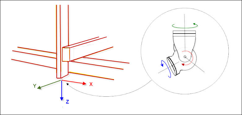
Examples of position kinematics include gantries (Kin_Gantry3) and tripods (Kin_Tripod_Lin, Kin_Tripod_Rotary). These kinematics can travel to any point or position, but cannot perform any number of orientations. The front coordinate system of a position kinematic system is referred to as a flange coordinate system. It defines the place where orientation kinematics are attached (figure on left).
Examples of orientation kinematics are Kin_CAxis, Kin_Wrist2, and Kin_Wrist3. These kinematics can result in a desired orientation of the TCP, but cannot reach any position (see figure on the right).
By combining both position kinematics and orientation kinematics, it is possible to travel any number of positions in the desired orientation, or the other way around.
Invalid combinations
Not every combination of position kinematics and orientation kinematics is possible because sometimes a unique inverse transformation cannot be determined. One example is a SCARA with two articulate joints as position kinematics and Kin_CAxis_Tool as orientation kinematics with a tool offset that is not 0 in the X- or Y-coordinate. The orientation of the flange coordinate system of the SCARA is not constant. It is rotated about the Z-axis relative to the 0 position. For the calculation of the inverse transformation, this rotation is not yet known, which makes it impossible to clearly determine the axis angles in this case.
Whether a combination is possible can be checked at runtime, as it depends on the parameterization of the kinematics. In this case, the error SMC_TRAFO_INVALID_COUPLING is issued.
Behavior when programming "impossible" orientations
In practice, it is often useful to be able to program orientations that are not available for the kinematics. As a simple example, consider a SCARA robot with a tool having one degree of freedom (rotation about the Z-axis). In principle, this robot can accept only orientations in which the tool points vertically downwards.
When positions should be traveled on a workpiece, it will be easily tilted from the X/Y-plane. The user teaches the workpiece and then programs the positions and orientations relative to the workpiece. The tilting of the workpiece results in orientations in which the tool direction is slightly tilted from the vertical.
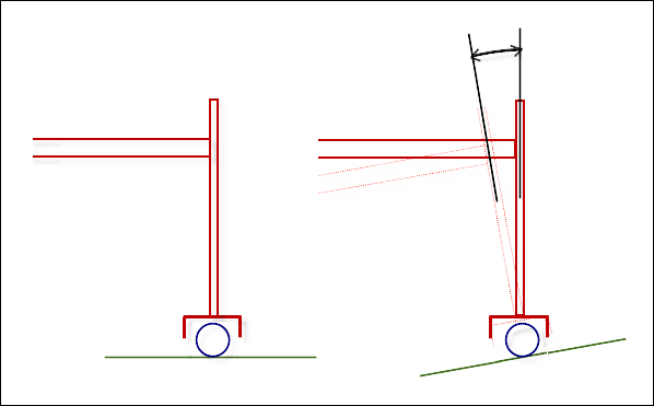
How do we deal with such an impossible and unreachable orientation? A drastic measure would be to report a workspace violation. However, as the example shows, this would make programming tedious. Therefore, the orientation kinematics (Kin_CAxis_Tool in this example) are implemented in such a way that they assume the nearest achievable orientation. In this example this means that the commanded orientation is tilted in such a way that the tool stands upright and this orientation is accepted.
The behavior can be reduced to the following rules (provided the position kinematics can position in all three spatial directions):
The position is always approached exactly (otherwise an error is reported).
The orientation is "projected" to the nearest accessible one if it cannot be reached.
When projecting the orientation, the tool direction has priority.
The difficulties described here arise because the orientation kinematics do not have the three degrees of freedom to achieve all desired orientations. This is the case with Kin_Wrist2 and Kin_CAxis, but not with Kin_Wrist3.
Additional difficulties arise when the position kinematics also do not have all spatial degrees of freedom. (This does not occur often in practice.) One example is the combination of Kin_Gantry2, a gantry that can be positioned in X/Y only, and with Kin_Wrist2, a tool with only two degrees of freedom. In this case, there are impossible orientations as well as impossible positions, because the Z-coordinate is already defined by the tool length and the position of the orientation axis. Therefore, we recommend that you do not use these kinds of combinations, but to program only attainable positions.
Remarks about customized kinematics
Users who want to create their own position or orientation kinematics have to implement the following additional interfaces in their kinematics function blocks:
For position kinematics: The interface
ISMPositionKinematics2with the methodsAxesToOrientationandGetOrientationImage.AxesToOrientationis an "abbreviated" forward transformation that calculates the orientation of the flange coordinate system from the axis values. It is necessary only for reasons of efficiency. For example, nothing has to be calculated with a gantry, but rather a constant orientation can be returned.GetOrientationImagereturns how the orientation of the flange coordinate system can change. This method is necessary only for checking whether orientation kinematics are compatible with the position kinematics.For orientation kinematics: The interface
ISMToolKinematics2with the methodsGetPositionFromOrientation2andIsCompatibleWithPosKin.GetPositionFromOrientation2calculates the vector between the flange coordinate system and TCP from the desired orientation (in MCS). This calculation is necessary for the inverse transformation of the combined kinematics. TheIsCompatibleWithPosKinmethod checks whether the orientation kinematics are compatible with the position kinematics.