Tab: Scaling/Mapping
On this tab, you can define the relationship between technical units (for example, millimeters or degrees) and the drive units (increments). Depending on the device description, the setting options are displayed simplified (parameter bHiresMode = TRUE), and/or scaling for linear motors may also be possible (parameter IsLinearMotor = TRUE). If necessary, you can also influence the mapping of cyclically transmitted drive objects to IEC variables.
Invert direction |
|
Precision (decimal digits) | Requirement: The device description specifies a simplified configuration dialog (parameter Number of decimal places for the user units of the increments to be scaled and transferred. For example, |
increments <=> motor turns | Number of increments that correspond to a given number of motor turns. You can see the parameter on the Configuration tab of the device editor. |
motor turns <=> gear output turns | Number of motor turns that correspond to a given number of gear output turns. |
gear output turns <=> units in application | Number of gear output turns that correspond to a unit in the application. |

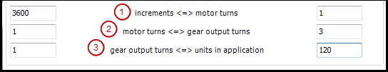
In the sample configuration, a drive that has 3600 increments for a motor turn is scaled so that the technical units of the application are straight angular degrees.
Note: These parameters are not available for Drive_PosControl. | |
Automatic mapping |
|