Creating Cams Programmatically
As of CODESYS SoftMotion version 4.17.0.0, the CamBuilder function block provides an interface for creating cams programmatically directly in the IEC application.
For more information, see the example: Creating Cams Programmatically
Using the CamBuilder function block (as of SM 4.17.0.0)
The following cam is created by default when a cam object is created in the device tree:
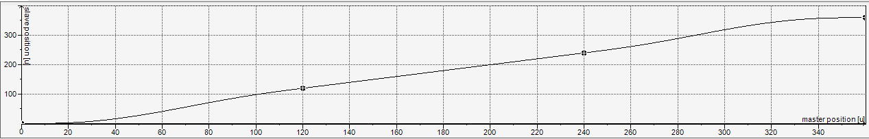
The cam consists of three fifth-degree polynomials with the following four boundary values:
X | Y | V | A |
|---|---|---|---|
0 | 0 | 0 | 0 |
120 | 120 | 1 | 0 |
240 | 240 | 1 | 0 |
360 | 360 | 0 | 0 |
To create this cam programmatically, an instance of the CamBuilder function block is first declared:
VAR
    camBuilder : SMCB.CamBuilder;
END_VAR
In the implementation part, the CamBuilder instance first has to be initialized. Three segments of type Poly5 can then be added using the Append method:
camBuilder.Init();

camBuilder.Append(
    SMCB.Poly5(
	SMCB.BoundImplicit(),
	SMCB.Bound(120, 120, 1)));
camBuilder.Append(
    SMCB.Poly5(
	SMCB.BoundImplicit(),
	SMCB.Bound(240, 240, 1)));
camBuilder.Append(
    SMCB.Poly5(
        SMCB.BoundImplicit(),
        SMCB.Bound(360, 360)));
The polynomials are defined via the left and right boundary conditions. In the example, the BoundImplicit function is always used for the left boundary. As a result, the right boundary condition of the previous segment is applied. If the BoundImplicit function is used as the left boundary for the first segment, then it starts at zero: in this example, with Poly5 segment at (X, Y, V, A) = (0, 0, 0, 0).
When the MC_CamTableSelect and MC_CamIn function blocks are used, the cam defined in the CamBuilder function block finally has to be converted into an MC_CamRef. There are two ways to do this, depending on where the CamBuilder is called:
Calling the CamBuilder in the bus task:
First, the declaration part must be extended by the corresponding instances:
VAR
    ...
    camRef : MC_CAM_REF;
    aCamSegments : ARRAY[1..3] OF SMC_CAM_SEGMENT;
END_VAR
Then the function block instance
MC_CAM_REFis initialized and written using theWritemethod of theCamBuilderfunction block.SMCB.InitCamRef(camRef, ADR(aCamSegments), XSIZEOF(aCamSegments)); camBuilder.Write(camRef);
Calling the CamBuilder in another task (multitask, multicore):
First, a multitask/multicore-safe instance of the cam is created in a GVL, which is accessed by both the bus task and the CamBuilder task.
VAR_GLOBAL
    safeCam : SMCB.CAM_REF_MULTICORE_SAFE;
END_VAR
Then the creation of the cam in the other task is started from the bus task.
To determine in the bus task when the new cam was written in the other task, the program remembers the
CamIdinSTATE_INIT_ONLINE_TABLE_MULTITASKbefore the cam is created.Then the creation of the cam is started in the other task in the
STATE_START_CREATE_ONLINE_TABLE_MULTITASKstate.Then, the created cam is read in the
STATE_READ_ONLINE_TABLE_MULTITASKstate.
PROGRAM BUS_TASK
VAR
    state : UDINT;
    error : SMC_ERROR;
    camIdBeforeCreate : UDINT;
    camSegments: ARRAY[0..99] OF SMC_CAM_SEGMENT;
    camRef: MC_CAM_REF;
END_VAR
VAR CONSTANT
    STATE_INIT_ONLINE_TABLE_MULTITASK : UDINT := 0;
    STATE_START_CREATE_ONLINE_TABLE_MULTITASK : UDINT := 10;
    STATE_READ_ONLINE_TABLE_MULTITASK : UDINT := 20;
    STATE_ERROR : UDINT := 1000;
END_VAR


CASE state OF
STATE_INIT_ONLINE_TABLE_MULTITASK:
    camIdBeforeCreate := GVL.safeCam.CamId;

    state := STATE_START_CREATE_ONLINE_TABLE_MULTITASK;

STATE_START_CREATE_ONLINE_TABLE_MULTITASK:
    CamBuilderTask.BuildCam := TRUE;

    state := STATE_READ_ONLINE_TABLE_MULTITASK;

STATE_READ_ONLINE_TABLE_MULTITASK:
    IF CamBuilderTask.Error THEN
        error := CamBuilderTask.ErrorId;
        state := state + STATE_ERROR;
    ELSIF GVL.safeCam.CamId <> camIdBeforeCreate THEN
        error := GVL.safeCam.GetCopy(
            camRef:= camRef,
            pCamSegments:= ADR(camSegments),
            arraySize:= XSIZEOF(camSegments));

        IF error = SMC_NO_ERROR THEN
            state := state + 10;
        ELSE
            state := state + STATE_ERROR;
        END_IF
    END_IF
END_CASE
In the CamBuilder task, the multitask/multicore-safe cam is written by calling
CamBuilder.WriteMulticoreSafe():PROGRAM CamBuilderTask VAR_INPUT BuildCam : BOOL; END_VAR VAR_OUTPUT Error : BOOL; ErrorId : SMC_ERROR; END_VAR VAR camBuilder : SMCB.CamBuilder; END_VAR IF BuildCam THEN BuildCam := FALSE; camBuilder.Init(); camBuilder.Append(SMCB.Poly5(SMCB.BoundImplicit(), SMCB.Bound(120, 120, 1))); camBuilder.Append(SMCB.Poly5(SMCB.BoundImplicit(), SMCB.Bound(240, 240, 1))); camBuilder.Append(SMCB.Poly5(SMCB.BoundImplicit(), SMCB.Bound(360, 360))); Error := camBuilder.IsErrorPending(errorID=> ErrorId); IF NOT Error THEN ErrorId := camBuilder.WriteMulticoreSafe(GVL.safeCam); Error := ErrorId <> SMC_NO_ERROR; END_IF END_IF
Implicit and explicit boundary conditions
An implicit boundary condition defined with BoundImplicit makes sure that the transition to the adjacent segment is as smooth as possible. To do this, the boundary condition of the adjacent segment needs to be explicitly defined using the Bound method. So if the left boundary condition of a segment is implicit, then the right boundary condition of the previous segment has to be explicit. Conversely, if the right boundary condition is implicit, then the left boundary condition of the subsequent segment has to be explicit.
The most common use case is presumably that only the right boundary conditions of the segments are explicitly specified, as in the example above. Due to the implicit left boundary conditions, the segment transitions are automatically as smooth as possible and there are no gaps in the definition area. The following example is a simple case where it is helpful to deviate from this approach:
The slave axis should travel at a constant velocity from position 20 to 100:
camBuilder.Append(
    SMCB.Line(
        SMCB.Bound(20, 20),
        SMCB.Bound(100, 100)));
Before and after this, a Poly5 segment is used for acceleration and deceleration:
camBuilder.Append(
    SMCB.Poly5(
        SMCB.BoundImplicit(),
        SMCB.BoundImplicit()));
camBuilder.Append(
    SMCB.Line(
        SMCB.Bound(20, 20),
        SMCB.Bound(100, 100)));
camBuilder.Append(
    SMCB.Poly5(
        SMCB.BoundImplicit(),
        SMCB.Bound(120, 120, 0)));
The cam defined in this way has unwanted acceleration and deceleration phases in the Poly5 segments (velocity in blue):
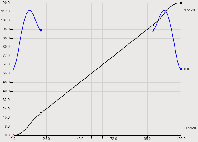
To avoid this, it is sufficient to adjust the master position in the segment of type Line (for example, that of the left boundary from 20 to 30 and that of the right boundary from 100 to 90):
...
camBuilder.Append(
    SMCB.Line(
        SMCB.Bound(30, 20),
        SMCB.Bound(90, 100)));
...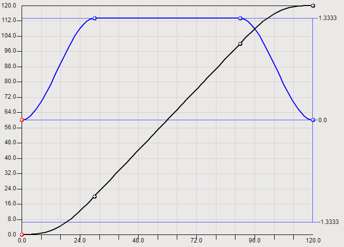
It is not necessary to adjust the segments of type Poly5 because they are automatically added to the line segment as smoothly as possible due to the boundary conditions defined using the BoundImplicit function.
Error Handling
The Append method of the CamBuilder function block returns TRUE when a segment has been successfully added, and returns FALSE if an error has occurred. After an error, no more segments can be added and the CamBuilder function block has to be reinitialized using the Init method. The cause of the error can be determined using the IsErrorPending method:
camBuilder.IsErrorPending(errorId=> errorId);
Manual creation of the data structure MC_CAM_REF (before SM 4.17.0.0)
Important
It is recommended to use the SM3_CamBuilder library as of CODESYS SoftMotion 4.17.0.0.
Data structures of cams
On project compile, the created cam data is converted internally into a global variable list. By clicking Display generated code in the cam editor, you can display the automatically created global variables.
Each cam is represented by the data structure MC_CAM_REF. You can access this data structure by means of the IEC program or by preprocessing functions and function blocks. It is available by the SM3_Basic library.
A function block that describes a cam can also be generated or populated by the IEC program at runtime.
Definition of the data structure:
TYPE mySMC_CAMTable_LREAL_10000_2 :
STRUCT
        Table: ARRAY[0..9999] OF ARRAY[0..1] OF LREAL;
        (* set all scaling definitions to 0 and 1
           result: all values of the table are not scaled *)
        fEditorMasterMin: REAL := 0;
        fEditorMasterMax: REAL := 1;
        fEditorSlaveMin: REAL := 0;
        fEditorSlaveMax: REAL := 1;
        fTableMasterMin: REAL := 0;
        fTableMasterMax: REAL := 1;
        fTableSlaveMin: REAL := 0;
        fTableSlaveMax: REAL := 1;
END_STRUCT
END_TYPE
Instantiating the data structure:
Cam: MC_CAM_REF;
Cam_PointArray : mySMC_CAMTable_LREAL_10000_2;
Calculating the cam:
Cam.byType:=2;
Cam.byVarType:=6;
Cam.nTappets:=0;
Cam.strCAMName:='myCAM';
Cam.pce:= ADR(CAM_PointArray);
FOR i:=0 TO 9999 DO
        (* example cam: master 0..360, slave 0..100,
           constant velocity *)
        Cam_PointArray.Table[i][0]:=UDINT_TO_LREAL(I)/10000 * 360;             (* X *)
        Cam_PointArray.Table[i][1]:=UDINT_TO_LREAL(I)/10000 * 100;             (* Y *)
END_FOR
Cam.nElements:=10000
Cam.xStart:=0.0;
Cam.xEnd:=360.0;
Manually generated cams
A cam can be created in an IEC program without using the cam editor.
Declaration:
VAR
i: INT;
CAM: MC_CAM_REF := (
        byType:=2, (* non-equidistant *)
        byVarType:=2, (* UINT *)
        nElements:=128,
        xStart:=0,
        xEnd:=360);
Table: SMC_CAMTable_UINT_128_2 := (
        fEditorMasterMin := 0, fEditorMasterMax := 360,
        fTableMasterMin := 0, fTableMasterMax := 6000,
        fEditorSlaveMin := 0, fEditorSlaveMax := 360,
        fTableSlaveMin := 0, fTableSlaveMax := 6000);
END_VAR
Implementation:
(* Create cam disk (example straight line); unambiguous *)
FOR i:=0 TO 127 DO
        Table.Table[i][0] := Table.Table[i][1] := REAL_TO_UINT(i / 127.0 * 6000);
END_FOR
(* Link pointer; must be done in every cycle! *)
CAM.pce := ADR(Table);
This generated cam can be specified in the MC_CamTableSelect function block and its output used again for MC_CamIn.
Compiling cam definitions
At compile time, variables of type MC_CAM_REF are created for a cam. They include a description of each segment of the cam. Data structures of this kind are passed to the MC_CamTableSelect function block. The structure is part of the SM3_Basic library.