Object: Logical I/Os (device editor)
Function: Configurator for logical I/Os
Call: Double-click on an object in the device tree under Logical I/Os
Tab: Safe configuration
Function: Configuration of the parameters for safe communication.
This Safe configuration dialog is only available for fail-safe I/Os.
Tip
Integer parameters can optionally be displayed in hexadecimal notation. This optional setting must be made in the device description file.
Tip
Changes made in the Safe configuration dialog are highlighted in red. Only the last change is marked here. All change markings are removed when the editor is closed.
In work | Changed |
Pin Information | Pinned |
The default values for the parameters originate from the respective device description file (SDD). | |
Name | Name of the parameter Example: |
Value | Example: 1 |
Symbolic value | Optional
|
Description | Optional Example: |
Unit | Optional |
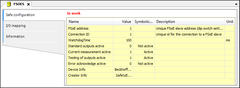
Name | Description |
|---|---|
FSoE address | Unique EtherCAT address of the module. A FSoE connection corresponds to one safe fieldbus device (or its logical I/Os). |
WatchdogTime | Watchdog time If the module does not respond within this time, then an error is issued. |
Connection ID | Unique connection number in the entire EtherCAT network |
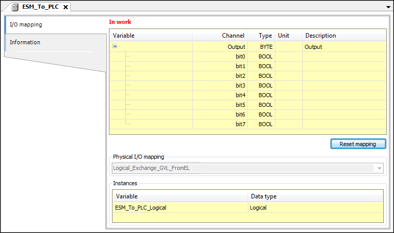
Tab: I/O mapping
Function: Defines the variables for the safety application to access the I/Os.
Tip
In CODESYS Safety for EtherCAT Safety Module, you can map I/O channels only to new variables. They cannot be mapped to existing variables.
Tip
The editor of the logical I/Os of standard devices has no Safe Configuration dialog. The configuration and the device parameterization are performed under the default application as in CODESYS standard.
Note
When a device has been assigned to the EtherCAT Safety Module, the mapping dialog of the device editor shows only this assignment and no longer the channel mapping to the variables of the main controller.
In work | Changed |
Pin Information | Pinned |
List of mapped variables | |
Variable | List of variables (tree view) Example: Note: Double-click the variable to edit it Changes made are marked in red. Only the last change is marked. All change markings are removed when the editor is closed. |
Channel | Non-editable information from the device description file (SDD file) Input: Variables mapped to input channels represent the corresponding input signals of the field device. They can be read. Output: Variables mapped to output channels can be written and set the output signals of the field device. |
Type | Non-editable information from the device description file (SDD file) IEC data type |
Unit | Non-editable information from the device description file (SDD file) |
Description | Non-editable information from the device description file (SDD file) |
Button: Reset mapping | Deletes all mapping variables specified in the table and resets the mapping of the physical device to the logical I/O. |
FSOES | Displays the standard application object which is connected to this logical I/O |
Variable | Instance name These variables are available to the safety application as global variables. An implicit global variable with the corresponding name and the data type specified in the Type column are created in the safety application for each input or output channel of an I/O module that a variable has been assigned. For a description of how to use the variables defined here, see: Using Logical I/Os Programmatically |
Data type | Example: |
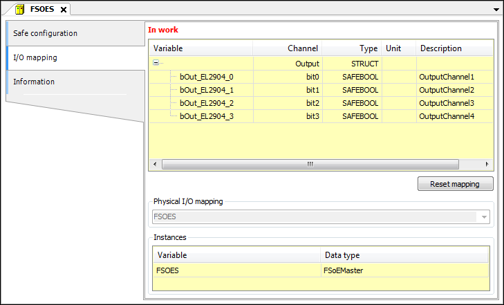
Changes made in the I/O Mapping dialog are highlighted in red. Only the last change is marked here. All change markings are removed when the editor is closed.
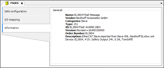
Tab: Information
Function: Shows information and, if applicable, an image of the respective logical I/O.
Listed as information: Name, Vendor, Categories, Type, ID, Version, Order number, and Description
The default values for the parameters originate from the respective device description file (SDD). | |
Name | Name of the logical I/O Example: |
Vendor | Example: Beckhoff |
Categories | Possible categories
|
Type | Optional Example: |
ID | Example: |
Version | Example: |
Order number | Example: |
Description | Example: |