Getting Started
A sample project with the CODESYS Safety for EtherCAT Safety Module add-on will be created here. The completed ECAT.projectarchive project can also be found in the CODESYS installation directory in the Projects\Applications subfolder.
Procedure
Creating a new project
Create a new standard project as usual, as described in Create standard project.
Click New Project.
Select the Standard Project template.
Specify a name and a storage location.
Dialog: New Project
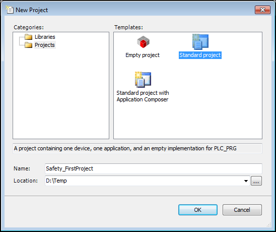
Click OK to close the dialog.
The Standard Project dialog opens.
Select CODESYS Control Win as the controller.
Select Structured Text as the language for the
PLC_PRGPOU.Dialog: Standard Project
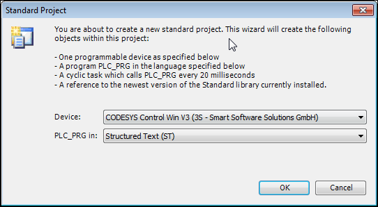
Click OK to confirm your settings.
The project has been created. All standard objects are displayed in the device tree.
Adapting the communication settings of the controller
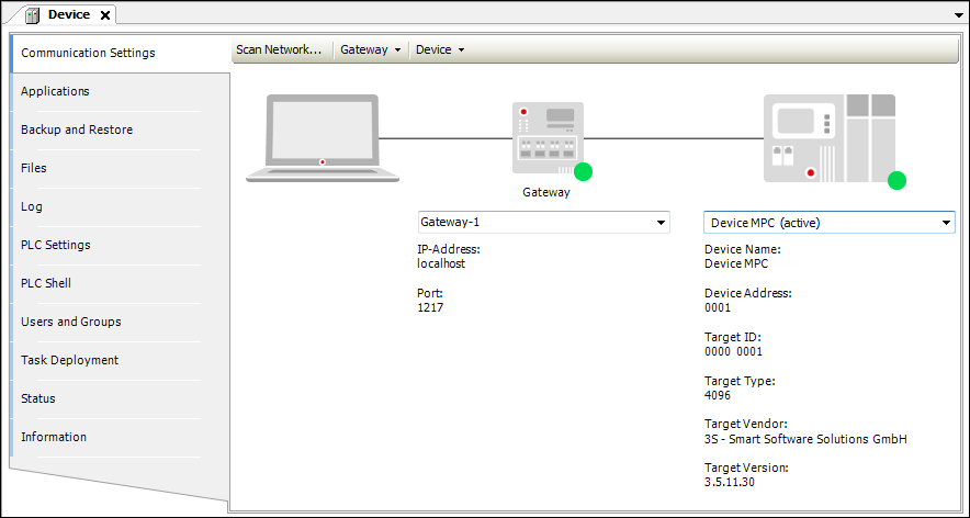
In the device tree, double-click the device.
The device editor opens on the right side.
Select the desired controller.
Communication settings of the device editor
Adding an EtherCAT Master to the device tree
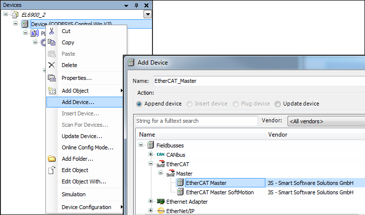
Right-click the controller to open its context menu and click Add Device.
The Add Device dialog opens.
Select the EtherCAT Master device and click Add Device.
The device is added.
Configuring the EtherCAT Master
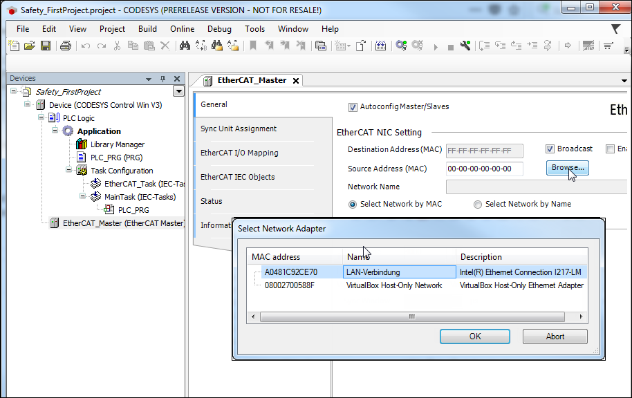
Double-click the object to open the configurator of the EtherCAT Master.
In the Select Network Adapter dialog, click the Select button and specify the desired adapter.
The EtherCAT Master is configured. The communication settings have been configured.
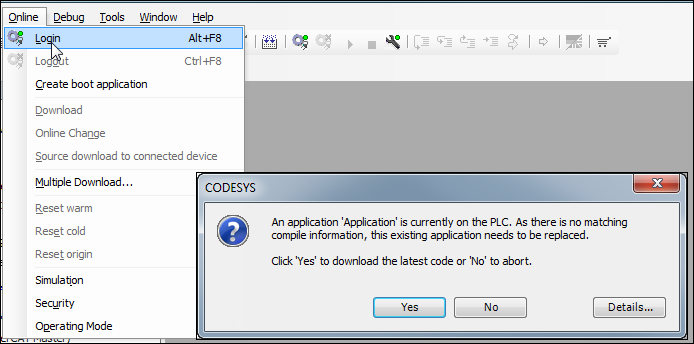
Login and download
Click .
The application on the controller is overwritten.
Log back out.
Scanning detected hardware
Click Scan For Devices.
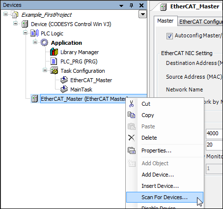
The devices available in the network are listed.
Click the Copy all devices to project button.
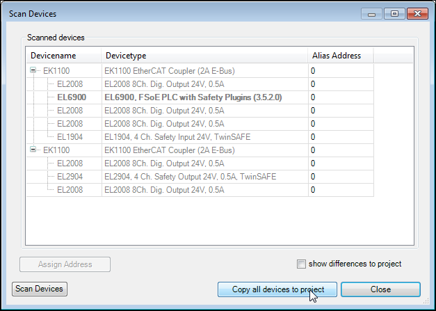
The hardware found is automatically transferred to the project and displayed in the device tree.
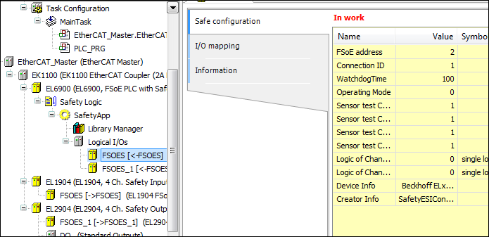
Setting the parameters of the logical I/O modules
Open the device editor of the EL1904 module and set the FSoE address (example: 2). This is the address which is also set on the device via DIP switches.
Open the device editor of the EL2904 module and set the FSoE address (example: 3). This is the address which is also set on the device via DIP switches.
Logical I/Os – Settings
Note
The connection ID must be parameterized in such a way that every logical I/O module has its own unique address.
This makes sure that the safe I/O module can detect errors caused by the incorrect forwarding of a FSoE telegram. The connection ID is therefore checked in the safe IO module.
The uniqueness is not checked by CODESYS.
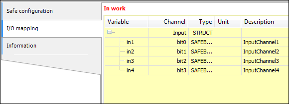
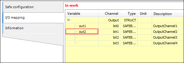
Defining the I/O mapping of the logical devices
Open the I/O Mapping tab.
Assign variables to the individual channels of the module.
EL1904 logical I/O mapping
EL2904 logical I/Os – I/O mapping
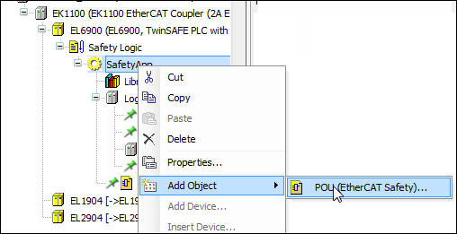
Programming a POU (program)
Click ).
The POU has been added.
Open the POU and drag the
FB_TWOHANDfunction block into the programming area of the editor. Pay attention to the Start here message.Connect the inputs and outputs of the function block to the variables as shown.
Programming area with the
FB_TWOHANDfunction block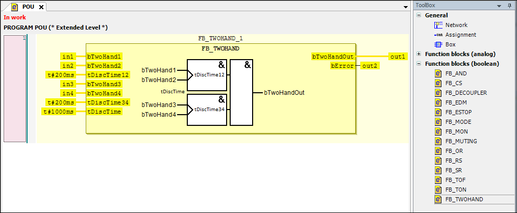
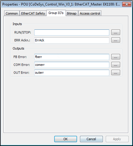
Setting of variables on the Group IOs tab of the
POUprogramThese variables control the state of the POU and can signal errors.
Open the properties of the recently created POU (right-click the POU in the device tree ) and configure the settings under Group IOs as shown.
POU – Properties
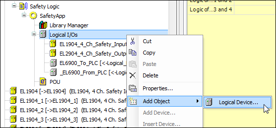
Adding logical devices for data exchange
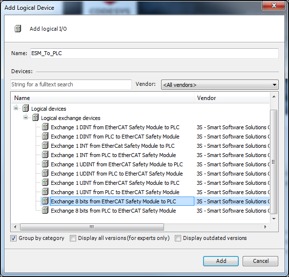
Open the Add Logical Device dialog (context menu of Logical I/Os → Add Object → Logical Device).
In the dialog, select the Exchange 8 bits from EtherCAT Safety Module to PLC device. Give it the name
ESM_To_PLC.Logical device – Exchange device
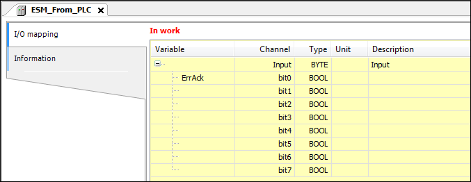
Add the Exchange 8 bits from the PLC to EtherCAT Safety Module logical device. Give it the name
ESM_From_PLC.
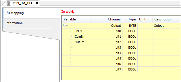
Defining the variables of exchange objects
Double-click the newly added logical devices to open the respective editor. Map the variables as shown below.
Logical device ESM_to_PLC: Variable definition
Logical device ESM_from_PLC: Variable definition
Adding global variable lists for logical exchange
Add GVLs for logical exchange to the device tree ().
Adding a logical exchange GVL
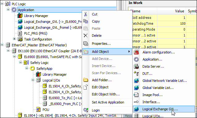
In the Add Logical Exchange GVL dialog, specify the name
FromESM.The new GVL is added to the device tree.
Double-click to open the editors.
The variables of the logical device
ESM_To_PLCare now mapped to this GVL in the lower area of the editor.GVL – Assignment of the logical I/Os
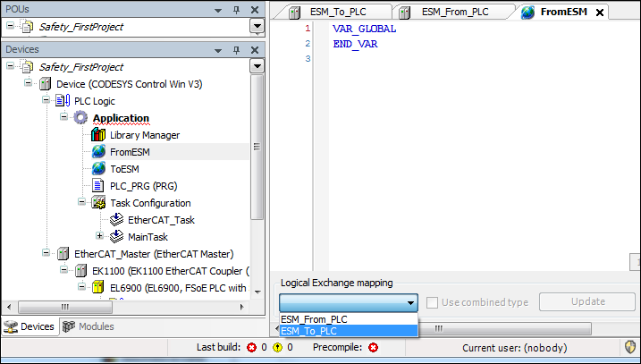
In a similar way, create the GVL
ToESMand connect it to the logical I/Os ofESM_From_PLC.
PLC_PRGprogramCreating the
PLC_PRGprogramThe
PLC_PRGprogram is used to read and write the variables of the safety application. TheFbErr,ComErr, andOutErrvariables have been added so that the states can be monitored. IfbAutostartis set, then theErrAckflag is set for one cycle in the case of an error in the safety block (detected byComErr) so that the error is acknowledged in the EtherCAT Safety Module.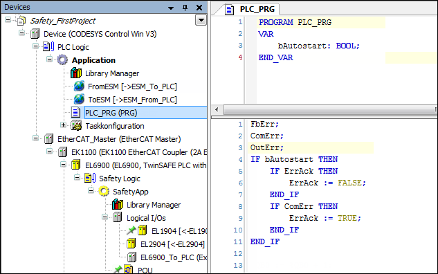
Transferring the standard application to controller
Finally, log in to the standard controller, transfer (download) the application, and start it.
The states of the variables can now be monitored in the online view.
Downloading the safety program
Now load the safety program to the EtherCAT Safety Module. To do this, open the module in the editor and click the Download Project button.
The login dialog opens.
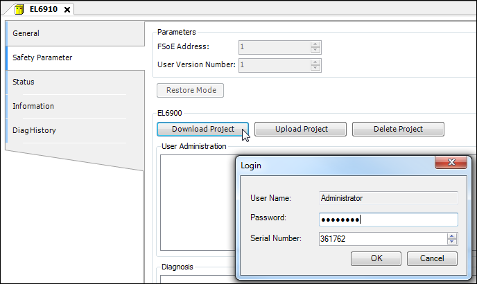
In this dialog, specify the name and password of a user which is entered in the user administration of the EtherCAT Safety Module, as well as the serial number of the EtherCAT Safety Module.
The default password is "
TwinSAFE".Starting the program on the EtherCAT Safety Module
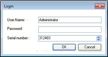
After the project comparison, specify the user name, password, and serial number of the EtherCAT Safety Module again in order to start the project.
After clicking OK to confirm, the safety program runs on the EtherCAT Safety Module.
Login
Now the POU can be opened in the editor and the inputs monitored.