FB_MUTING
Description Function Block
The FB_MUTING function block implements an intended suppression of the safety function, for example to transport material into the safety area. The output of the function block remains set even though the connected sensors are interrupted.
The bMuting<n> inputs are used to check that they are actuated in a defined order.
Muting is activated with the bEnable input. If the input is FALSE, then an interruption of the guard leads to the FB output being switched off immediately. In other cases, only when the muting sequence is violated.
The bSequentialInputs input can be used to define whether each of the 2 inputs are checked in parallel or sequentially. In order to prevent the bouncing of the muting signals and therefore a violation of the muting sequence, a filter time tFilterTime (max. 500 ms) can be set for the muting inputs.
Furthermore, it is possible to use tMaxMutingTime to monitor the maximum duration of the muting process. The muting process starts with a TRUE signal of the first muting input and ends with the FALSE signal of the last muting input. The value can be configured to a maximum of 10 minutes or set to 0, which corresponds the monitoring being deactivated. During this period, the bMutingActive output of the function block is set.
The guard (AOPD – Active Opto-electronic Protection Device), such as a light curtain, is connected to the bOSSDIn(x) inputs.
The feedback signals can be connected to the EDM inputs. The inputs are deactivated in the default setting.
The direct outputs and the outputs delayed by up to 30 seconds are switched via the bMuteOut and bMuteDelOut outputs.
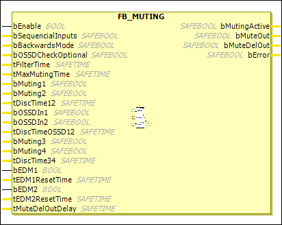
If bMuting2 and tDiscTime12 are deleted, then bMuting1 is used as a 1-channel input. This operating principle applies to bMuting4 and bOSSDIn2.
Name | Data Type | Initial Value | Description, Parameter Values |
|---|---|---|---|
|
|
|
|
|
|
| Determines whether two inputs are checked in parallel ( |
|
|
| If the input is
A muting sequence must be completed before a new sequence (perhaps in the other direction) can be started. The input is not supported by the EL6900. |
|
|
| If the input is The input is not supported by the EL6900. |
|
|
| Filter time to avoid bouncing of the inputs |
|
|
| Maximum duration of the muting process |
|
|
| The muting inputs are used to check whether they are actuated in a defined order. 1st input channel: The Negation command can be used to specify whether a normally closed contact (safe state is requested for |
|
|
| 2nd input channel: Same behavior as |
|
|
| Discrepancy monitoring time for muting input 1 and 2 |
|
|
| The guard (AOPD – Active Opto-electronic Protection Device), such as a light curtain, is connected to the
The Negation command can be used to specify whether a normally closed contact (safe state is requested for |
|
|
|
If the discrepancy time is not equal to 0, then the 1st and 2nd |
|
|
| Discrepancy monitoring time for the |
|
|
| 3rd input channel or 1st input channel of the 2nd input group. Otherwise corresponds to |
|
|
| 4th input channel or 2nd input channel of the 2nd input group. Otherwise corresponds to |
|
|
| Discrepancy monitoring time for muting input 3 and 4 |
|
|
|
|
|
|
| If not equal to The input is not supported by the EL6900. |
|
|
|
|
|
|
| If not equal to The input is not supported by the EL6900. |
|
|
| Delay time between 1st output channel and 2nd output channel |
Name | Data Type | Initial Value | Description, Parameter Values |
|---|---|---|---|
|
|
| 1st output channel: Indicates the current muting process by |
|
|
| 2nd output channel: Indicates the safe state by |
|
|
| 3rd output channel: Indicates the safe state by |
|
|
|
|