FB_MON
Description Function Block
The FB_MON function block can be used, for example, to implement a safety door circuit with up to four (bMonIn(x)) inputs. Using the Negation command, each of the four inputs can be implemented as a normally closed contact (break contact – FALSE requests the safe state) or as a normally open contact (make contact – TRUE requests the safe state). As soon as an input requests the safe state, the first output (bMonOut) immediately enters the safe state ("FALSE") and the second output (bMonDelOut) enters the safe state after a configurable time delay. The option of linking the FB output to several outputs means that several outputs which switch off immediately (FB_Mon) or switch off with a delay (bMonOut) can be implemented with just one bMonDelOut.
In addition, there are two bSecure inputs which can be used to bypass the request for the safe state via the bMonIn inputs. The bSecure inputs can also be implemented both as normally closed contacts (break contact) and as normally open contacts (make contact).
The Restart input of the FB can be activated (active or manual restart) by linking the input. An open bRestart input will create a compiler error. If the restart is supposed to be executed automatically (non-active or automatic restart), then the bRestart input must be deleted. In order to quit the safe state of the outputs, a FALSE–TRUE–FALSE signal sequence must be recognized at the Restart input in the case of active restart. In the case of non-active restart, the safe state is quit as soon as the bMonIn input or the bSecure input no longer request the safe state.
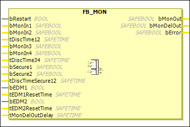
Furthermore, a feedback loop can be activated for each of the two outputs. In a feedback loop, the bMonOut output is fed back to the bEDM1 input and the bMonDelOut output is fed back to the bEDM2 input via external wiring. The bEDM inputs are checked as soon as the safe state should be quit. When Restart is activated, if the bEDM inputs do not have the TRUE signal state, then the function block enters the error state and sets the bError output to TRUE. When Restart is deactivated, the FB_MON remains in the safe state if the bEDM inputs do not have TRUE signal state at the moment of restarting. As a result, an bEDM error can be recognized only if the manual restart is active. The error state can be quit again only by a FALSE-TRUE-FALSE signal sequence at the ERR_ACK input of the associated POU (TwinSAFE group).
Furthermore, two inputs (bMonIn1 and bMonIn2, bMonIn3 and bMonIn4, bSecure1 and bSecure2) can be combined in each case to form input pairs in which the signal states of the two inputs may deviate from each other only within a configurable discrepancy time tDiscTimexx. If this discrepancy time is exceeded for an input pair, then the FB_MON function block also enters the error state.
If bMonIn2 and tDiscTime12 are deleted, then bMonIn1 is used as a 1-channel input. This operating principle applies to bMonIn4 and bSecure2.
Name | Data Type | Initial Value | Description, Parameter Values |
|---|---|---|---|
|
|
| In the case that the manual restart is active, when the FB is started or when an input has requested the safe state, the If the manual restart is not active, then this input is not used. Both starting and quitting the safe state take place automatically as soon as no inputs request the safe state any longer. |
|
|
| 1st input channel: The Negation command can be used to specify whether a normally closed contact or a normally open contact is linked with this input.
|
|
|
| 2nd input channel: Same behavior as |
|
|
| Discrepancy time |
|
|
| 3rd input channel or 1st input channel of the 2nd input pair, otherwise corresponds to |
|
|
| 4th input channel or 2nd input channel of the 2nd input pair, otherwise corresponds to |
|
|
| Discrepancy time |
|
|
| If If the discrepancy time is activated or used, then |
|
|
|
|
|
|
| Discrepancy time for |
|
|
|
|
|
|
| If not equal to The input is not supported by the EL6900. |
|
|
|
|
|
|
| If not equal to The input is not supported by the EL6900. |
|
|
| Delay time for the output of the safe state at |
Name | Data Type | Initial Value | Description, Parameter Values |
|---|---|---|---|
|
|
| 1st output channel: The safe state corresponds to |
|
|
| 2nd output channel: The safe state corresponds to |
|
|
|
|