FB_ESTOP
Description Function Block
The FB_EStop function block can be used to implement an emergency stop circuit with up to eight emergency stop inputs (bEStopIn1 – bEStopIn8). Each of the eight inputs can be negated using the Negation command from the context menu. As soon as an input requests the safe state, the first output (EStopOut) immediately enters the safe state ("0") and the second output (EStopDelOut) enters the safe state after a configurable time delay. The option of linking the FB output to several outputs means that several outputs which switch off immediately (bEStopOut) or switch off with a delay (bEStopDelOut) can be implemented with just one FB_EStop. In order to quit the safe state of the outputs, a 0->1->0 signal sequence must be recognized at the Restart input.
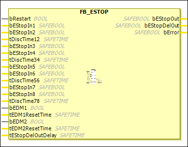
Furthermore, a feedback loop can be activated for each of the two outputs. In a feedback loop, the bEStopOut output is fed back to the bEDM1 input and the bEStopDelOut output is fed back to the bEDM2 input via external wiring. The EDM inputs are checked as soon as the safe state is supposed to be quit by means of a 0->1->0 signal sequence at the Restart input. If the EDM inputs do not have the signal status "1", then the FB_EStop function block enters the error state and sets the bError output to 1. The error state can be exited only by a 0->1->0 signal sequence at the ERR_ACK input of the associated POU (TwinSAFE group).
Furthermore, two inputs (bEStopIn1 and bEStopIn2, bEStopIn3 and bEStopIn4, bEStopIn5 and bEStopIn6, as well as bEStopIn7 and bEStopIn8) can be combined in each case to form input pairs in which the signal states of the two inputs may deviate from each other only within a configurable discrepancy time (tDiscTimexx input). If this discrepancy time is exceeded for an input pair, then the FB_EStop function block also enters the error state. In the error state of the FB, the outputs adopt the safe state "0".
If bEStopIn2 and tDiscTime12 are deleted, then bEStopIn1 is used as a 1-channel input. This operating principle applies to all input pairs.
Name | Data Type | Initial Value | Description, Parameter Values |
|---|---|---|---|
|
|
| On Start (when the associated POU (TwinSAFE group) is started) or Restart (when an input has requested the safe state), the signal sequence 0->1->0 must be recognized at the |
|
|
| 1st input channel: The Negation command can be used to specify whether the input behaves as a normally closed contact (break contact – safe state is requested with logic |
|
|
| 2nd input channel: Same behavior as If the discrepancy time is not equal to |
|
|
| Discrepancy time for input group 1 (In1+In2) |
|
|
| 3rd input channel or 1st input channel of the 2nd input pair, otherwise corresponds to |
|
|
| 4th input channel or 2nd input channel of the 2nd input pair, otherwise corresponds to |
|
|
| Discrepancy time for input group 2 (In3+In4) |
|
|
| 5th input channel or 1st input channel of the 3rd input pair, otherwise corresponds to |
|
|
| 6th input channel or 2nd input channel of the 3rd input pair, otherwise corresponds to |
|
|
| Discrepancy time for input group 3 (In5+In6) |
|
|
| 7th input channel or 1st input channel of the 4th input pair, otherwise corresponds to |
|
|
| 8th input channel or 2nd input channel of the 4th input pair, otherwise corresponds to |
|
|
| Discrepancy time for input group 4 (In7+In8) |
|
|
|
|
|
|
| If not equal to The input is not supported by the EL6900. |
|
|
|
|
|
|
| If not equal to The input is not supported by the EL6900. |
|
|
| Delay time for the output of the safe state at |
Name | Data Type | Initial Value | Description, Parameter Values |
|---|---|---|---|
|
|
| 1st output channel: The safe state corresponds to logic |
|
|
| 2nd output channel: The safe state corresponds to logic |
|
|
|
|