Tab: Safe Configuration
The bus-specific configuration parameters for safe communication are listed on the Safe Configuration tab of the device editor for the logical I/Os. The parameters originate from the device description file of the respective device and are automatically loaded into the editor when adding the corresponding logical I/O. With some bus systems further device-specific parameters can be listed here.
Caution
Fieldbus-specific requirements for the setting of specific parameters are to be considered. See: Logical I/O of an F-Device, Logical I/O of a Safety Device
The top line ( ) contains the pin information of the safety application, or In Work if the object version deviates from the pinned version, or if the safety application has not yet been pinned.
In the adjacent area ( ) the parameters are illustrated in tabular form with Name, Value, Symbolic value, Description, and optional Unit.
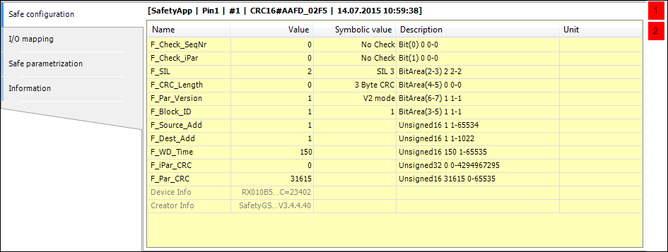
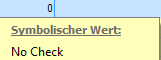
By double-clicking the Value field of a parameter whose value is editable, a new value can be entered in the field. In the case of parameters with symbolic values, double-clicking the Value field opens a message window showing an explanation of the value.
Parameters that cannot be edited are represented with a brighter font color (in the figure above: Device Info and Creator Info).
Change markers
If values of fields in the parameter table are changed, then these and all other fields that change as a result are marked red. Only the last change is marked. All change markings are removed when the editor is closed.
Configuration parameters for PROFIsafe (F-Parameters), see: Logical I/O of an F-Device)
Configuration parameters for FSoE, see: Logical I/O of a Safety Device